

Retaining walls play a crucial role in residential and light commercial projects by preventing soil erosion and providing structural stability. A well-designed retaining wall ensures the safety and longevity of the surrounding structures while effectively managing changes in elevation.
This comprehensive guide aims to assist structural engineers, building designers, and architects in the United States by focusing on American standards and key structural considerations for retaining wall design.
Understanding Retaining Walls
Retaining walls are structures designed to resist lateral pressure from soil and hold it in place. They are commonly used in situations where there is a significant change in elevation, such as terraced landscapes or sloping sites. Retaining walls not only prevent soil erosion but also create usable spaces, increases property value, and enhances the aesthetic appeal of a project.
There are various types of retaining walls suitable for residential and light commercial projects. These include gravity walls, cantilever walls, sheet pile walls, anchored walls, and segmental retaining walls. Each type has its own advantages and design considerations based on factors such as soil conditions, site requirements, and budget constraints.
To ensure the effectiveness of a retaining wall, several basic principles should be considered. Proper drainage is essential to prevent water buildup behind the wall, which can increase hydrostatic pressure and compromise stability. Adequate load distribution across the wall and consideration of the retained soil's properties are also vital for maintaining structural integrity.
American Standards for Retaining Wall Design
Designing retaining walls in accordance with American standards is crucial to ensure compliance, safety, and structural performance. The International Building Code (IBC) is the primary reference for construction and design standards in the United States. The IBC provides guidelines for structural design, materials, and construction practices, including those specific to retaining walls.
The American Society of Civil Engineers (ASCE) also publishes guidelines and standards related to retaining walls. ASCE 7, "Minimum Design Loads for Buildings and Other Structures," provides provisions for calculating loads on structures, including retaining walls. ASCE 7-16 is the latest version and is widely adopted in the industry.
Complying with these standards is essential to meet safety requirements and ensure the structural integrity of retaining walls. They specify load-bearing capacity, design considerations for various site conditions, and construction practices to minimize the risk of failure.
Structural Considerations for Retaining Wall Design
When designing retaining walls, structural engineers, building designers, and architects must consider several critical factors.
Site Analysis
Thorough site analysis is crucial to understanding the soil properties, water tables, and slope stability. The properties of the retained soil, including its cohesion, angle of internal friction, and potential for settlement, must be assessed to determine appropriate design parameters. Additionally, knowledge of the water table is essential to assess hydrostatic pressure and potential drainage requirements.
Stability analysis of the slopes adjacent to the retaining wall is also important. Understanding the site's geological conditions, including the presence of clay, sand, or rock formations, helps determine the appropriate wall type and design.
Load Calculations
Accurate load calculations are vital for designing a structurally sound retaining wall. Loads can be categorized into dead loads, live loads, surcharges, and lateral earth pressure and these must always be considered in the design of a retaining wall. Although it's not common, wind loads might also play a role, for example, if there is a large exposed area on the top of the wall due to the installation of billboards.
Dead loads include the weight of the wall itself, backfill material, and any permanent structures built on top of the wall. Live loads represent transient loads such as vehicle loads or people's weight in proximity to the retaining wall.
Surcharges refer to additional loads on top of the retained soil, such as parking lots or driveways. The magnitude and distribution of surcharge loads should be considered to ensure stability and adequate load-bearing capacity.
Lateral earth pressure is the force exerted by the soil against the retaining wall. It depends on the soil properties, the angle of internal friction, and the wall's geometry. Various methods can be used to determine lateral earth pressure, including Rankine's theory, Coulomb's theory, and the use of earth pressure coefficients.
Proper consideration of all these loads is essential to ensure that the retaining wall can safely resist the imposed forces and maintain stability over time.
Reinforcements and Anchoring Systems
Reinforcements are often necessary to enhance the structural integrity of retaining walls. Common reinforcement techniques include the use of geosynthetic materials, such as geogrids or geotextiles, which provide tensile strength and improve soil-structure interaction.
Anchoring systems are employed to prevent the wall from overturning or sliding due to lateral forces. Anchors can be either passive or active.
- Passive anchors, such as deadmen or ground anchors, rely on their weight and frictional resistance to provide stability.
- Active anchors, such as soil nails or tiebacks, use tensioned elements to resist lateral forces.
The selection of appropriate reinforcements and anchoring systems depends on the specific project requirements, soil conditions, and the desired level of stability.
Construction Techniques
Proper construction techniques are essential for the successful implementation of retaining walls. Excavation and foundation preparation must be carried out according to the design specifications, ensuring proper compaction of the soil and appropriate drainage measures.
Construction joints and interfaces between different elements of the retaining wall should be carefully designed and constructed to maintain structural continuity and prevent water infiltration. The use of suitable backfill materials, compaction methods, and geotechnical measures, such as drainage pipes or weep holes, can significantly contribute to the long-term performance of the retaining wall.
Regular inspections during construction are crucial to ensure that the retaining wall is built according to the design plans and specifications. Any deviations or potential issues should be addressed promptly to maintain structural integrity and compliance with American standards.
Design Examples
Segmental Retaining Wall Example By Hand Calculations
Design Requirements:
- Wall height: 8 feet
- Live load: 50 psf
- Surcharges: 10 psf
- Soil properties: Cohesive soil (clayey)
Step 1: Site Analysis
Determine the soil properties through laboratory testing:
Cohesive soil, angle of internal friction (φ) = 25 degrees.
Step 2: Load Calculations
Calculate the lateral earth pressure (P) using Rankine's earth pressure theory: P = (H * γ * Ka) + (H * γ * Kp)
Where:
- H = Wall height = 8 feet
- γ = Unit weight of soil = 120 pcf
- Ka = Active earth pressure coefficient = (1 - sin φ) / (1 + sin φ) = (1 - sin 25) / (1 + sin 25) ≈ 0.288
- Kp = Passive earth pressure coefficient = (1 + sin φ) / (1 - sin φ) = (1 + sin 25) / (1 - sin 25) ≈ 2.874
- P = (8 * 120 * 0.288) + (8 * 120 * 2.874) = 2,210.56 psf
Calculate the design loads on the wall:
Dead load: Assuming a weight of 120 pcf for the wall materials:
Dead load = Wall height * Unit weight of wall materials Dead load = 8 * 120 = 960 psf Total design load = Dead load + Live load + Surcharges Total design load = 960 + 50 + 10 = 1,020 psf
Step 3: Wall Dimensions
Determine the dimensions of the wall based on the design loads and soil conditions. Let's assume a segmental block width of 12 inches.
Assuming a uniform pressure distribution, the base width (B) can be estimated using Rankine's formula: B = (P * H) / (2 * γ * Ka) B = (2,210.56 * 8) / (2 * 120 * 0.288) ≈ 64.23 inches.
Considering the block width of 12 inches, the number of blocks required per row can be determined: Number of blocks per row = B / Block width Number of blocks per row = 64.23 / 12 ≈ 5.35 ≈ 6 blocks (rounded up)
Step 4: Reinforcement Design
Geogrid reinforcement is commonly used in segmental retaining walls. The spacing and length of the geogrid layers depend on the design requirements and soil conditions. Let's assume a geogrid spacing of 24 inches and a length equal to the wall height.
Step 5: Anchoring System
In this example, we assume the retaining wall does not require an anchoring system since the wall height is within the typical limits for segmental retaining walls.
Step 6: Construction Considerations
Proper excavation, base course installation, interlocking of segmental blocks, compaction, and drainage features should be implemented according to the manufacturer's guidelines and local building codes.
Please note that this is a simplified example to demonstrate the steps involved in retaining wall design. In practice, a detailed analysis, considering various factors such as soil properties, groundwater conditions, and local regulations, is required for a comprehensive and accurate design. It is crucial to consult a qualified structural engineer or retaining wall specialist for a thorough analysis.
Cantilever Retaining Wall with Anchoring System Example By Hand Calculations
Design Requirements:
- Wall height: 10 feet
- Live load: 40 psf
- Surcharges: 15 psf
- Soil properties: Granular soil (sandy)
Step 1: Site Analysis
Determine the soil properties through laboratory testing:
Granular soil, angle of internal friction (φ) = 30 degrees.
Step 2: Load Calculations
Calculate** the lateral earth pressure (P)** using Rankine's earth pressure theory: P = (H * γ * Ka) + (H * γ * Kp)
Where:
- H = Wall height = 10 feet γ = Unit weight of soil = 110 pcf
- Ka = Active earth pressure coefficient = (1 - sin φ) / (1 + sin φ) = (1 - sin 30) / (1 + sin 30) ≈ 0.366
- Kp = Passive earth pressure coefficient = (1 + sin φ) / (1 - sin φ) = (1 + sin 30) / (1 - sin 30) ≈ 1.732
- P = (10 * 110 * 0.366) + (10 * 110 * 1.732) = 2,374.2 psf
Calculate the design loads on the wall: Dead load: Assuming a weight of 125 pcf for the wall materials: Dead load = Wall height * Unit weight of wall materials Dead load = 10 * 125 = 1,250 psf Total design load = Dead load + Live load + Surcharges Total design load = 1,250 + 40 + 15 = 1,305 psf
Step 3: Wall Dimensions
Determine the dimensions of the wall based on the design loads and soil conditions.
Let's assume a concrete retaining wall with a base width-to-height ratio of 0.6.
Determine the base width (B) using the formula: B = (P * H) / (2 * γ * Ka) B = (2,374.2 * 10) / (2 * 110 * 0.366) ≈ 46.36 feet.
Calculate the stem thickness (t) using the base width-to-height ratio: t = 0.6 * H = 0.6 * 10 = 6 feet
Step 4: Reinforcement Design
Design the reinforcement for the cantilever retaining wall.
Let's assume the reinforcement consists of vertical steel bars placed at 24-inch intervals in the stem and horizontal reinforcement (stirrups) placed at 2-foot intervals.
Determine the required steel area (A_s) for the stem using the moment equation: A_s = (M * d) / (f * h)
Where:
- M = Moment due to the design loads
- d = Effective depth of the stem
- f = Allowable stress in steel
- h = Height of the stem
Assuming a design moment of 50,000 ft-lbf/ft, an effective depth of 9 feet, and allowable stress of 40,000 psi:
A_s = (50,000 * 9) / (40,000 * 6) ≈ 1.125 square inches
Select a suitable reinforcing bar size based on the calculated area.
Step 5: Anchoring System
Design and install an anchoring system to provide additional stability for the cantilever retaining wall.
Since the wall height exceeds the typical limits for a cantilever retaining wall, an anchoring system is required to provide additional stability. Let's consider the use of soil nails as the anchoring system.
Determine the spacing and length of the soil nails based on the design requirements and soil conditions. Assume a soil nail spacing of 4 feet and a nail length equal to the wall height.
Calculate the pullout resistance of the soil nails using the following equation:
Pullout resistance= Bond strength * Perimeter * Length
Where:
Bond strength = Cohesion of soil * Bond length Perimeter = 2 * (Nail diameter + Shotcrete cover)
Let's assume a cohesive soil with a cohesion of 300 psf, a bond length of 8 feet, a nail diameter of 1 inch, and a shotcrete cover of 2 inches:
Bond strength = 300 * 8 = 2,400 psf Perimeter = 2 * (1 + 2) = 6 inches.
Pullout resistance = 2,400 * 6 * 10 = 144,000 lb
Check the stability of the retaining wall with the soil nails, ensuring that the pullout resistance exceeds the required resistance.
Step 6: Construction Considerations
During construction, follow proper excavation techniques, including proper slope stability measures and installation of the base course.
Install the soil nails at the specified spacing and length, ensuring proper bonding with the surrounding soil.
Construct the retaining wall using suitable materials and techniques, considering factors such as drainage, backfill compaction, and integration of the anchoring system.
Please note that this example is for illustrative purposes only and does not replace the need for a comprehensive and detailed analysis by a qualified structural engineer.
Retaining wall design involves various factors and considerations that are specific to each project and site conditions. It is crucial to consult a professional engineer to perform the necessary calculations and design the retaining wall according to the specific requirements of your project and compliance with applicable codes and standards.
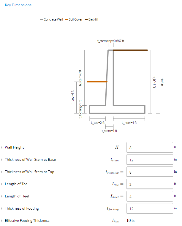
Cantilever Retaining Wall with Anchoring System Example Using ClearCalcs
ClearCalcs Retaining Wall Calculators can design various types of retaining walls.
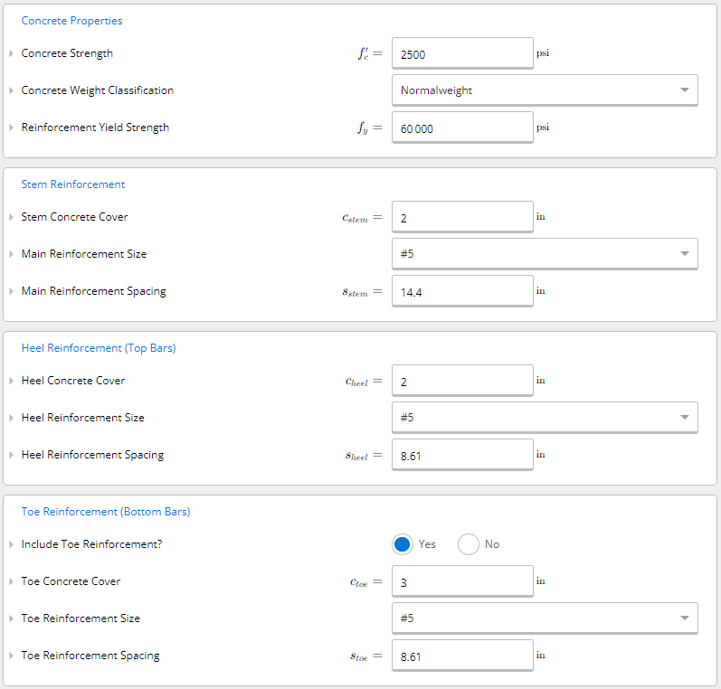
The example above can be input into ClearCalcs for faster results, more detailed design checks, and an instant ability to adjust inputs and assess their impact on the governing capacity. First, the key dimensions, surcharge, soil, concrete, and reinforcement properties are inputted into the calculator.
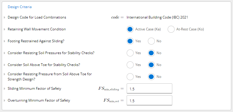
The design criteria are then specified by the user. Each criterion can be clicked on for further information to explain what it is and where it can be found in the standards. As our example is using an anchoring system, the footing will be restrained against sliding.
The summary outputs determine total utilization. If any of the factors of safety are exceeded, and the action is greater than the capacity (utilization > 100%), then the user can adjust the key dimensions, surcharge, soil, concrete, and reinforcement properties to find an appropriate design by iteration with instantaneous results.
Case Studies and Best Practices
Real-life case studies provide valuable insights into successful retaining wall designs and highlight the challenges faced and innovative solutions implemented. By examining these case studies, structural engineers, building designers, and architects can learn from past experiences and apply best practices to their own projects.
Case Study 1: Big Dig Retaining Wall, Boston, Massachusetts
Key Challenge: The Big Dig project in Boston faced the challenge of constructing a retaining wall to support the highway while preserving historical structures and minimizing disruptions to traffic. Retaining walls are commonly used in civil infrastructure to facilitate immediate changes in level, such as in the construction of ‘The Big Dig’ below.
![[BLOG] retaining-wall-the-big-dig.jpg](https://cdn.prod.website-files.com/67189a2b26762b3b096e3184/673d80dc63aaac9e330b20e8_BLOG_retaining_wall_the_big_dig_179362f5aa.jpeg)
Image 1: Central Artery Project "The Big Dig" (Reference)
Innovative Solution: The project team used a combination of soldier pile and lagging walls, along with ground improvement techniques such as jet grouting and soil nailing. This approach allowed for efficient excavation, provided structural stability, and minimized impacts on surrounding structures.
Lessons Learned: The integration of multiple retaining wall systems and ground improvement techniques can provide effective solutions for complex projects. Thorough analysis and coordination among various disciplines are crucial for successful implementation.
Case Study 2: Redi-Rock Retaining Wall, Madison, Wisconsin
Key Challenge: The project required a retaining wall system that could accommodate varying slopes and provide stability for a commercial development site while maintaining the aesthetic of a rolling landscape.
An example of Redi-Rock is shown below.
![[BLOG] retaining-wall-redi-rock.jpg](https://cdn.prod.website-files.com/67189a2b26762b3b096e3184/673d80dc63aaac9e330b20eb_BLOG_retaining_wall_redi_rock_a7bbf651f4.jpeg)
Image 2: An example of Redi-Rock Retaining Wall (Reference)
Innovative Solution: The Redi-Rock retaining wall system was employed due to its flexibility, ease of installation, and aesthetic appeal. The system allowed for the construction of curved walls, seamless integration of stairs and corners, and efficient use of space.
Lessons Learned: The selection of an appropriate modular retaining wall system can offer design flexibility and cost-effectiveness. Proper installation techniques, including accurate leveling and alignment, are essential for achieving optimal performance.
Best Practices and Lessons Learned
- Site Analysis: Conduct a thorough site analysis, including an assessment of soil properties, slope stability, water tables, and groundwater conditions. This information informs the design and selection of appropriate retaining wall systems.
- Collaboration: Foster collaboration among the project team, including structural engineers, geotechnical engineers, architects, and contractors. Effective communication and coordination throughout the design and construction phases are key to successful retaining wall projects.
- Drainage: Incorporate proper drainage features into the design to manage water runoff and prevent excessive hydrostatic pressure behind the retaining wall. This helps maintain the stability and longevity of the structure.
- Quality Materials: Use high-quality materials that are suitable for the specific site conditions and load requirements. Ensure compliance with applicable codes and standards for material selection and testing.
Emerging Techniques, Materials, and Technologies
- Reinforced Soil Systems: Reinforced soil systems, such as geosynthetic reinforcement, offer an efficient and sustainable solution for retaining walls. These systems combine the strength of soil and reinforcing elements to provide stability and reduce material requirements.
- Green Walls: Green walls, also known as living walls or vegetated retaining walls, provide both structural support and aesthetic appeal. These systems incorporate vegetation to enhance biodiversity, improve air quality, and reduce stormwater runoff.
- Geosynthetic Reinforced Walls: Advances in geosynthetic materials and technology have resulted in the development of geosynthetic reinforced walls. These systems utilize high-strength geotextiles or geogrids to reinforce soil mass, allowing for the construction of taller and more cost-effective retaining walls.
- Innovative Construction Techniques: Innovations such as precast concrete panels, rapid construction methods, and 3D printing technology are being explored to enhance the efficiency and speed of retaining wall construction while maintaining structural integrity.
Conclusion
Retaining wall design is a critical aspect of residential and light commercial projects. Adhering to American standards and considering key structural factors ensures the safety, compliance, and durability of retaining walls.
By conducting a thorough site analysis, accurately calculating loads, selecting appropriate reinforcements and anchoring systems, and employing proper construction techniques, professionals can design retaining walls that withstand lateral forces and maintain long-term stability. Compliance with the International Building Code (IBC) and the guidelines provided by the American Society of Civil Engineers (ASCE) is essential to meet safety requirements and ensure structural integrity.
Staying updated with emerging techniques, materials, and technologies is crucial in the field of retaining wall design. The industry is constantly evolving, and new advancements can enhance the efficiency and longevity of retaining walls. Participating in industry conferences, seminars, and online forums facilitates knowledge exchange and keeps professionals abreast of the latest trends.
In conclusion, retaining wall design to American standards requires a thorough understanding of structural considerations, compliance with codes and standards, and the application of best practices.
By prioritizing safety, compliance, and durability, professionals can design retaining walls that effectively prevent soil erosion, provide structural stability, and contribute to the success of residential and light commercial projects.
References:
- International Building Code (IBC)
- American Society of Civil Engineers (ASCE) Standards
- Geotechnical Engineering Principles and Practices by Donald P. Coduto
- Design of Retaining Walls Embedded in Stiff Clay by Richard J. Finno and Timothy D. Stark
- Soil Mechanics in Engineering Practice by Karl Terzaghi and Ralph B. Peck
Seismic Retrofit Series: URM Insights for US and Canada Engineers
August 5th at 1 pm Eastern Time (ET)
Save your spot →Written by:

Kyle Conway
.svg)
Reviewed by:


.png)
