

This guide serves as a resource for structural engineers, covering the fundamentals of timber connections according to the design standard AS 1720.1, the scope of the standard, and the key design parameters for timber screwed connections. It provides the advantages of timber screwed connections, their use cases, design parameters as well as design examples by hand and using ClearCalcs.
Note: This design guide is intended to be informative but may not be prescriptive or accurate for your situation. Compliance with AS 1720.1(2010) must be ensured in every design, and the designer must have the appropriate qualifications depending on the jurisdiction in which they are designing.
Advantages of timber screwed connections
Timber screwed connections offer several advantages in a wide range of structural design projects including light commercial projects or residential timber-framed construction:
- Ease of installation: Quick to install with minimal tools and without pre-drilling in many cases.
- Strong holding power: High resistance to pull-out and lateral loads, providing a secure connection between structural members.
- Adjustability: Can be easily removed and reinstalled, ideal for temporary structures or adjustments.
- Reduced splitting: Screws create less splitting in timber than nails, especially near edges.
- Durability: High-quality screws (e.g., stainless steel or galvanized) resist corrosion, extending connection life.
- Versatility: Suitable for a wide range of timber design applications, including framing, decking, and hybrid timber-metal connections.
- Precision: Offers accurate alignment for tight, stable joints, critical in load-bearing applications.
- Enhanced load capacity: Screws can withstand various loading types, making them suitable for structural and non-structural applications.
Common applications for timber screwed connections
- Timber framing and structural joints: Screwed connections are commonly used in framing for connecting beams, studs, and joists to provide structural stability in timber-framed buildings.
- Timber cladding and facades: Screws are frequently used to attach timber cladding panels to structural frames or battens, providing a secure and weather-resistant attachment.
- Flooring and decking: Screwed connections are popular for securing floorboards to floor joists, decking boards, and subfloor components due to their ability to resist pull-out and provide a strong, reliable bond.
- Roof trusses and rafters: Screws are used to connect truss members, rafters, and purlins in roofing applications, as they offer high resistance to wind uplift and other forces.
- Wall plates and timber connectors: Screwed connections are used to attach wall plates, metal timber connectors (like brackets and hangers), and reinforcement hardware in load-bearing structures. For more information about other fastener types, see our guide on timber nail connections.
- Timber-to-metal connections: Screws with specific heads and threads are used to attach timber to steel components, such as fixing timber beams to steel posts in hybrid construction.
- Furniture assembly and cabinetry: Screws are commonly used in cabinetry, joinery, and furniture assembly for connecting timber components due to their ease of installation and adjustability.
- Timber bridges and boardwalks: In outdoor structures like timber bridges and boardwalks, screws are often used due to their durability and high holding power, especially in treated timber.
- Temporary timber structures: Screws allow for quick assembly and disassembly in temporary structures, like formwork, scaffolding, and exhibition setups.
- Repair and retrofitting: Screwed connections are useful in repair applications where damaged timber needs reinforcement or replacement, as they are easy to install in existing structures.
AS 1720.1 Timber Structures
AS 1720.1 provides structural design methods for timber and engineered wood products used in building construction. It covers:
- Structural design principles for timber and wood-based materials.
- Requirements for designing connections, including bolted, nailed, and screwed joints.
- Load-carrying capacity criteria for connections subjected to various loads.
- Provisions for different timber species, moisture conditions, and service environments.
- The standard applies to all types of solid timber, including softwood and hardwood, as well as engineered wood products such as plywood, laminated veneer lumber (LVL), and glued laminated timber (glulam). Specifically, for bolted connections, AS 1720.1 provides guidelines for joint types, spacing, and bolt sizes to achieve optimal performance.
In this article we will cover the design procedure for timber coach screwed connections in accordance with AS 1720.1(2010).
Design parameters
Timber properties
Joint Group
Joint Groups categorize timber species based on their density, hardness, and connection performance. The performance is primarily focused on the timber's capacity to hold fasteners like nails, bolts, or screws under loading conditions.The Joint Groups used in AS 1720.1:2010 include the following:
- JD1 to JD6: Used for seasoned (dry) timber.
- JD1 is the strongest, usually representing high-density, seasoned hardwoods.
- JD6 is the weakest, usually for lower-density, seasoned softwoods.
- J1 to J6: Used for unseasoned (green) timber.
- J1 is the strongest, usually high-density, unseasoned hardwoods.
- J6 is the weakest, usually low-density, unseasoned softwoods.
Grain direction
The strength of timber varies depending on loading parallel or perpendicular to the grain, influencing the design of bolted connections.
Load conditions
Axial Load: Loads acting in the same direction as the fastener.
Shear Load: Loads acting perpendicular to the fastener.
Combined Loads: When axial and lateral loads are combined, AS 1720.1 provides interaction equations to ensure the connection can safely support both loads simultaneously.
Connection detailing
End and edge distances: AS 1720.1 specifies minimum distances from the screws center to the end or edge of timber members to prevent splitting.
Screw spacing: Minimum and maximum spacing between screws is critical to ensuring even load distribution across the connection. Excessive spacing can cause uneven loading, while tight spacing may reduce load-carrying capacity.
Embedment length: The length of the screw embedded in the timber affects the withdrawal capacity and lateral load capacity. This is generally a function of the screw diameter and timber properties.
Service factors and duration of load
AS 1720.1 adjusts the design capacity based on load duration, with different factors for permanent, short-term, and instantaneous loads. These adjustments ensure the connection’s longevity.
Environmental factors: Exposure conditions, including weathering and potential decay in untreated timber, are accounted for with adjustment factors. For example, an outdoor bolted connection may require corrosion-resistant screws and larger safety factors.
Safety and capacity factors
AS 1720.1 uses safety factors to account for uncertainties in material properties and construction variability. Typical factors range between 0.6 and 0.9 for timber connections.
Design procedure
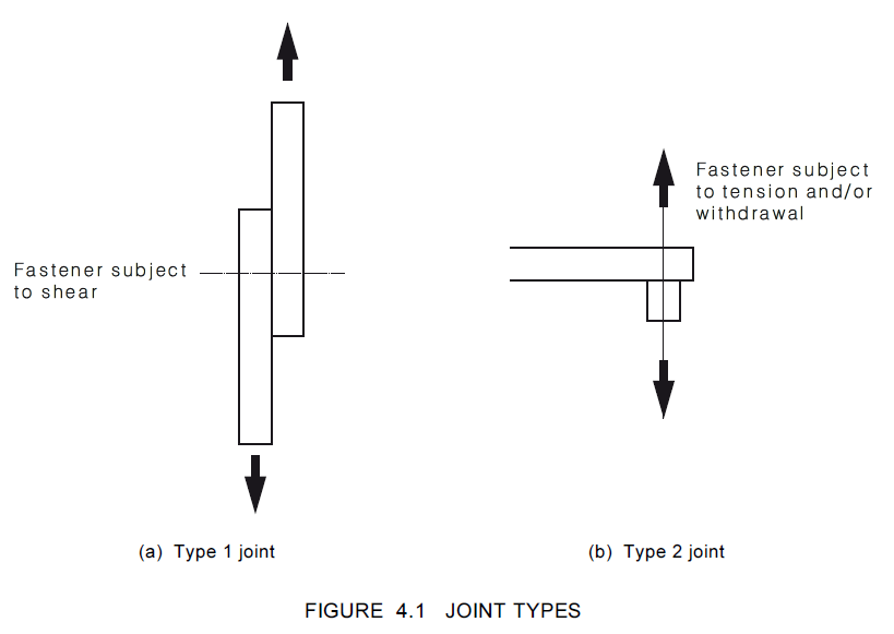
Step 1: Determine joint type
There are two joint types:
- Type 1 joint where fasteners subject to shear loads where the fastener is into the side or end grain of connected members
- Type 2 joint where fasteners subject to axial loads where the fastener is installed into the side or end grain of connected members
Step 2: Determine characteristic capacity of screws
Type 1 Joints
The second step is to determine if the fastener is in side grain or end grain as depicted in Figure 4.2 of A S1170.1(2010).

Side Grain (Type 1 Joints)
As per Clause 4.4.5.1 of AS 1720.1 the characteristic capacity (Qsk) for a Type 1 joint for coach screws lateral loads (shear) in side grain shall be calculated as if they were bolts in accordance with Clause 4.4.2.4 of AS 1720.1:
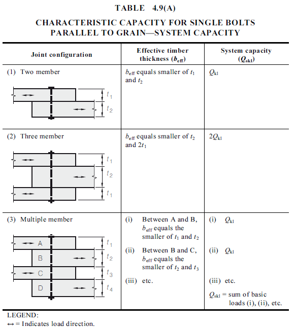
a) For systems loaded parallel to grain:
$Q_{sk}=Q_{sk1}$
Where:
$Q_{sk1}$ is given in Table 4.9(A) of AS 1720.1
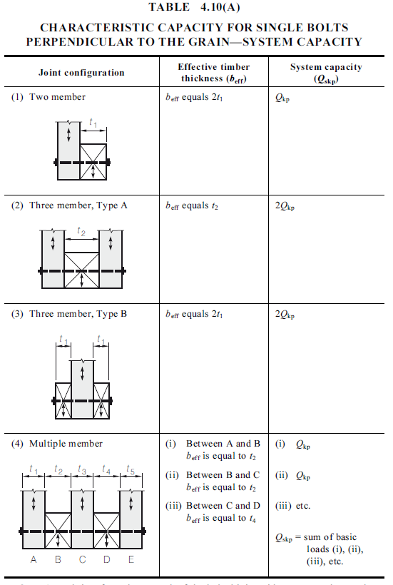
b) For systems loaded perpendicular to the grain:
$Q_{sk}=Q_{skp}$
Where:
$Q_{skp}$ is given in Table 4.10(A) of AS 1720.1
c) For systems loaded at an angle to the grain, (θ):
$$Q_{sk}=\frac{Q_{sk1}Q_{skp}}{Q_{sk1}sin^2 (\theta)+Q_{skp}cos^2 (\theta)}$$
The system capacity parameters are determined from AS 1720.1(2010) Table 4.9(B-C) and Table 4.10 (B-C).
In a two-member joint, the thinner member shall have a minimum thickness of three times the shank diameter of the coach screw.
Screws must always be turned into place (never hammered).
As per Clause 4.4.2.1a(v) of AS 1720.1(2010) timber thicknesses and coach screw lengths as shown in Figure 4.6(a) of AS 1720.1(2010) shall be such that:
a) the thickness of outermost member, t1 >3D; and
b)the depth of penetration into the second member (tp), for species groups is:
- J1, JD1, J2, JD2, JD3 ........................................................... tp >7D;
- J3, JD4 ................................................................................. tp >8D;
- J4, JD5 ......................................................................... tp >10D; and
- J5, J6, JD6 .......................................................................... tp >12D.

End Grain (Type 1 Joints)
The characteristic capacities for coach screws, laterally loaded in the end grain shall not exceed 60% of the values determined in accordance with Clause 4.5.2.1(a). The modification factor k13 accounts for end grain effects in the calculation.
Type 2 Joints
As per above, the first step is to determine if the fastener is in side grain or end grain.
Side Grain (Type 2 Joints)
As per Clause 4.5.2.2a of AS 1720.1(2010), withdrawal loads from side grain (see Figure 4.4(a)) The characteristic capacities for coach screws, driven by hand or machine, axially loaded in withdrawal from the side grain of unseasoned timber are given in Table 4.13(A) and of seasoned timber are given in Table 4.13(B).


End Grain (Type 2 Joints)
The characteristic capacities for coach screws in type 2 joints, laterally loaded in the end grain shall not exceed 60% of the values determined in accordance with Clause 4.5.2.2(a). The modification factor k13 accounts for end grain effects in the calculation.
Step 3: Determine the maximum tensile capacity
As per Clause 4.5.2.3 in AS 1720.1(2010), the maximum tensile capacity for a coach screw subject to direct axial loading shall not exceed the value appropriate to the diameter, as given in Table 4.14.

Step 4: Determine design capacity of coach screwed connection
Type 1 Joint
The design capacity (Nd,j) for a Type 1 joint containing n screws in shear to resist lateral
loads, as illustrated in AS 1720.1 (2010) Table 4.9 and Table 4.10, shall satisfy the following.
$N_{d,j}\ge N^*$
Where
$$N_{d,j}=\theta k_1k_{13}k_{16}k_{17}nQ_{sk}$$
$\theta $=capacity factor (Clause 2.3 AS 1720.1(2010)), 0.6 is most conservative
$k_1$=the factor for duration of load for joints (Clause 2.4.1.1 AS 1720.1(2010)), 0.57 is most conservative
$k_{13}$=1.0 for screws in side grain, 0.6 for screws in end grain
$k_{16}$=1.2 where load transfer is through close fitting holes into metal side plates, 1.0 otherwise
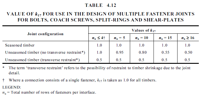
$k_{17}$=factor for multiple coach screwed joint given in Table 4.12 AS 1720.1(2010) shown below
$n$=total number of screws in connection resisting design action effect in shear
$Q_{sk}$=characteristic capacity as per Step 2 above
If you would like to see a worked example for a Type 1 joint, check out our article on Design Guide for Timber Bolted Connections to Australian Standards which follows a nearly identical design process to that for a screwed connection.
Type 2 Joint
The design capacity (Nd,j) for a Type 2 joint in which coach screws are axially loaded in withdrawal shall satisfy:
$N_{d,j}\ge N^*$
Where
$$N_{d,j}=min(nN_{d,tc^,}\theta k_{13}l_pnQ_{k^,} k_1k_7nf'_{pj}A_w)$$
$N^*$=design action effect in direct tension produced by strength limit states
$n$=total number of coach screws in connection
$N_{d,tc}$=design maximum tensile capacity of coach screw as per Table 4.14 in AS 1720.1(2010)
$\theta$=capacity factor (Clause 2.3 AS 1720.1(2010)), 0.6 is most conservative
$k_1$=the factor for duration of load for joints (Clause 2.4.1.1 AS 1720.1(2010)), 0.57 is most conservative
$k_7$=length of bearing factor as per Table 2.6 AS 1720.1(2010)
$k_{13}$=1.0 for screws in side grain, 0.6 for screws in end grain
$l_p$=depth of thread penetration into the innermost member
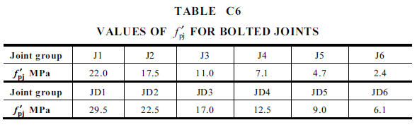
$f'_{pj}$=characteristic bearing capacity for timber in joints as per AS 1720.1(2010) Table C6
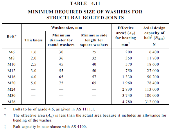
$A_w$=effective area of washer for bearing as per AS 1720.1(2010) Table 4.11
$Q_k$=characteristic capacity as per Step 2 above
Step 5: Specify spacings, edge and end distances for screws
Clause 4.5.4 of AS 1720.1(2010) states that the edge, end and between-fastener spacings are not less than those shown in Figure 4.9 as per AS 1720.1(2010) Clause 4.4.4, which is the same for bolts.
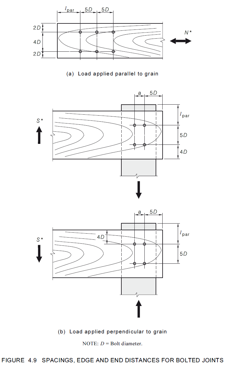
End Distance (lpar)
As per AS 1720.1(2010) Clause 4.4.4.2, the required end distance (lpar) shall be at least 8D in tension joints in unseasoned timber, 7D in tension joints in seasoned timber, and 5D in compression joints and in joints subject to bending moment for both moisture conditions. It is appropriate to use lesser end distances in tension joints provided the characteristic capacity is reduced in proportion to the reduction in end distance. In no case shall the end distance for tension joints be less than 6D for unseasoned timber and 5D for seasoned timber.
Spacing between screws perpendicular to load (a)
As per AS 1720.1(2010) Clause 4.4.4.3, the distance, a, shall be at least 2.5D for a b/D ratio of 2, and it shall be increased proportionately so that it is at least 5D for a b/D ratio of 6 or more, where b is the effective thickness of the member loaded perpendicular to the grain.
Loads acting at an angle to the grain
As per AS 1720.1(2010) Clause 4.4.4.4, for loads acting at an angle 0° to 30° to the grain, the spacings, edge and end distances shall be taken as for loads parallel to the grain. For loads acting at an angle of 30° to 90° to the grain, the spacings, edge and end distances shall be taken as for loads acting perpendicular to the grain.
Step 6: Specify washers
The washer size for screws is given in AS 1720.1(2010) Table 4.11 which is the same for bolts. Note: Ensure axial design capacity for screws is retrieved from Table 4.14, not Table 4.11.
Timber screwed connection design by hand calculation
Design a type 2 timber screwed connection that will connect two 90x45 MGP12 timbers for withdrawal from end grain. The screwed joint is for a timber residential building and is subjected to an axial load (tension) of 2kN dead load and 1kN live load.
Step 1: Determine joint type
This problem has the fastener subjected to tension/withdrawal so it is a Type 2 Joint as per Figure 4.1 in AS 1720.1(2010).
Step 2: Determine characteristic capacity of screws
MGP12 has a joint group of JD4 as per Table H3.1 in AS 1720.1(2010).

This connection is a type 2 joint in end grain. The characteristic capacities for coach screws in type 2 joints, laterally loaded in the end grain shall not exceed 60% of the values determined in accordance with Clause 4.5.2.2(a). The modification factor k13 accounts for end grain effects in the calculation.
As per Clause 4.5.2.2a of AS 1720.1(2010), withdrawal loads from side grain (see Figure 4.4(a)) The characteristic capacities for coach screws, driven by hand or machine, axially loaded in withdrawal from the side grain of seasoned timber are given in Table 4.13(B). Using the JD4 joint group and the smallest screw size, we get our characteristic capacity as 83N/mm of penetration.

Step 3: Determine the maximum tensile capacity
As per Clause 4.5.2.3 in AS 1720.1(2010), the maximum tensile capacity for a coach screw subject to direct axial loading shall not exceed the value appropriate to the diameter, as given in Table 4.14, for a 6mm screw is 3900N.
Step 4: Determine design capacity of coach screwed connection
The design capacity (Nd,j) for a Type 2 joint in which coach screws are axially loaded in withdrawal shall satisfy:
$N_{d,j}\ge N^*$
Where
$$N_{d,j}=min(nN_{d,tc^,}\theta k_{13}l_pnQ_{k})$$
Where
$N^*$=1.2*Dead load +1.5*Live load=(1.2*2000)+(1.5*1000)=3900N
$n$=total number of coach screws in connection
$N_{d,tc}$=design maximum tensile capacity of coach screw as per Table 4.14 in AS 1720.1(2010)=3900N
$\theta$=capacity factor (Clause 2.3 AS 1720.1(2010)), 0.6 is most conservative
$k_{13}$=0.6 for screws in end grain
$l_p$=depth of thread penetration into the innermost member=30mm for 45mm thick member
$Q_k$=83N/mm characteristic capacity as per Step 2 above
By transposing:
$$n\ge max(\frac{N^*}{N_{d,tc}},\frac{N*}{\theta k_{13}l_pQ_k})=max(\frac{3900}{3900},\frac{3900}{0.6*0.6*30*83})=max(1,4.35,24.52)$$
Therefore with 6mm diameter screws, we need 5 screws in the connection.
If we want to up the size of the screws to 12mm screws. The below parameters will change.
$N_{d,tc}$=design maximum tensile capacity of coach screw as per Table 4.14 in AS 1720.1(2010)=17400N
$Q_k$=104N/mm characteristic capacity as per AS 1720.1(2010) Table 4.13(B)
The number of screws required will be:
$$n\ge max(\frac{N^*}{N_{d,tc}},\frac{N*}{\theta k_{13}l_pQ_k})=max(\frac{3900}{17400},\frac{3900}{0.6*0.6*30*104})=max(0.22,3.47)$$
Therefore with 12mm diameter screws, we need 4 screws in the connection.
Note: in this example we have assumed crushing under the head does not pose a limit. Consider if this assumption is suitable for your project, if not ensure it is checked.
Step 5: Specify spacings, edge and end distances and washer size for screws
Clause 4.5.4 of AS 1720.1(2010) states that the edge, end and between-fastener spacings are not less than those shown in Figure 4.9 as per AS 1720.1(2010) Clause 4.4.4, which is the same for bolts.
End Distance (lpar)
As per AS 1720.1(2010) Clause 4.4.4.2, the required end distance (lpar) shall be at least 7D in tension joints in seasoned timber. Therefore we will adopt an end distance of 30mm based on the 6mm screw size.
Spacing between screws perpendicular to load (a)
As per AS 1720.1(2010) Clause 4.4.4.3, the distance, a, shall be at least 5D for a b/D ratio of 6 or more, where b is the effective thickness of the member loaded perpendicular to the grain. We have a b/D ration of 9 (45mm/6mm) so we will adopt a spacing of 5D = 30mm.
Specify washers
The washer size for screws is given in AS 1720.1(2010) Table 4.11 which is the same for bolts. For 6mm screws we will use a washer size of 30mm.
Timber bolted connection design using ClearCalcs
ClearCalcs provides comprehensive structural calculation tools that streamline the timber connection design process.
Design a type 2 timber screwed connection that will connect two 90x45 MGP12 timbers for withdrawal from end grain. The screwed joint is for a timber residential building and is subjected to an axial load (tension) of 2kN dead load and 1kN live load.
Step 1: Populate the applied loads

Step 2: Fill in the known design parameters
Next, under the key properties section, detail the known parameters, such as joint type and screw position (Type 2), the building category (Category 1 - House), the supported and supporting member grade & dimensions (90 x 45 MPG12) using the member selector tool as well as the depth of penetration into the supporting member (30mm).

Step 3: Iterate screw patterns and sizes to find a conforming design
Next, trial small screw sizes with a configuration that fits in with the dimensions of the two connected timber joints widths.
If it is not possible to reasonably fit in a screw arrangement within the width of the connected members, the screw size should be increased until an arrangement can be found.
It’s best to discuss the proposed screw arrangement with the builder to ensure it is constructible.
In this example, we have found two screws in each direction spaced at 30mm achieves a compliant design.
The key is to ensure that the utilisation of the capacity remains below 100%. A good target for load utilisation is 80% as it nicely balances a factor of safety with a structurally efficient design.

It can be useful in this step to ask what size screws they have in stock, because an arrangement may be able to be found for those screws which is a great way to deliver value for your client.
By ClearCalcs providing instantaneous feedback for the load utilisation of different screw arrangements, designers can find the most efficient solution or provide a number of compliant solutions to their customer to ease constructability on site.
Step 4: Export your calculation to append to your design
Many jurisdictions require the engineer to provide detailed calculations to meet regulatory compliance. Some clients even specify this as a requirement of the design.
ClearCalcs automatically exports the calculations completed in the background in accordance with AS 1720.1(2010) to save you time and ensure there are no calculation errors.

Conclusion
This guide to designing timber screwed connections according to AS 1720.1 (2010) covers essential parameters, design examples by hand and using ClearCalcs for safe and efficient building design.
By adhering to AS 1720.1 guidelines and relevant legislation in the jurisdiction you are designing in, engineers can ensure that timber structures meet performance and safety requirements in various loading and environmental conditions.
ClearCalcs can greatly speed up the design process leading to faster, more efficient designs, delivering better results for your organisation and the end client. ClearCalcs ensures your calculations are compliant with standards and the calculators get updated as standards get revised by the governing authority, meaning your design will always be checked for compliance against the appropriate metrics, without you needing to adjust your procedure.
Start your free trial today.
Seismic Retrofit Series: URM Insights for US and Canada Engineers
August 5th at 1 pm Eastern Time (ET)
Save your spot →Written by:

Kyle Conway
.svg)
Reviewed by:


.png)
