

Introduction
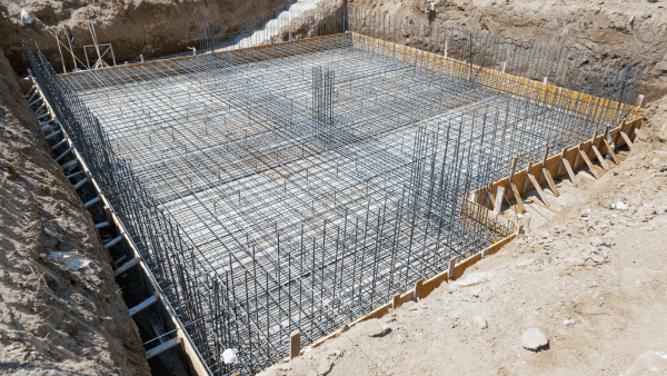
Reinforced concrete slabs (or concrete floor slabs) are a fundamental element in the construction of buildings and structures, providing a durable and versatile platform for both residential and commercial applications.
In Australia, the structural design of reinforced concrete slabs adheres to the guidelines and specifications outlined in Australian Standard AS 3600 - Concrete Structures.
This article provides a comprehensive overview of reinforced concrete slab design, with a focus on Australian standards and practices. It is intended for civil engineers, architects, and construction professionals who are involved in the design and construction of buildings and structures in Australia.
What is a Reinforced Concrete Slab?
A reinforced concrete slab is a flat, horizontal structural element that supports loads and distributes them to the underlying foundation or structure.
These slabs are commonly employed in various applications, including floors, roofs, balconies, and pavements.
The primary purpose of reinforcing the concrete in slabs is to enhance its structural capacity, durability, and resistance to cracking and deflection. This reinforcement typically consists of steel bars (rebar) or mesh embedded within the concrete.
Types of Reinforced Concrete Slabs and Their Application
Reinforced concrete slabs can be categorized into several types based on their design and application. The choice of slab type depends on factors such as the intended use, structural requirements, and environmental conditions.
The most common types of reinforced concrete slabs include the following:
One-Way Slab
A one-way slab is supported on two opposite sides and is designed to carry loads primarily in one direction. It is suitable for applications where the longer span is much greater than the shorter span, such as in the design of floors in buildings.
Two-Way Slab
A two-way slab is supported on all four sides and distributes loads in both the longitudinal and transverse directions. Two-way slabs are commonly used in larger spans, where both dimensions are relatively equal, as in the case of floor systems in high-rise buildings.
Flat Slab
Flat slabs are a variation of two-way slabs that lack the use of beams. Instead, they have a flat soffit (underside) and rely on increased slab thickness and column capitals to transfer loads. Flat slabs offer flexibility in design and are often used in commercial and industrial structures.
Waffle Slab
Waffle slabs incorporate a grid-like pattern of ribs and beams in their design, creating a waffle-like appearance on the soffit. These slabs are efficient for large, open spaces and have the advantage of reducing the amount of concrete used.
Slab on Ground
Slabs on the ground are used for outdoor applications such as pavements, driveways, and industrial yards. They are typically unreinforced or lightly reinforced to withstand environmental factors, such as temperature changes and soil movement.
Suspended Slab
Suspended slabs are used for elevated floors in buildings. These slabs are supported by beams or walls and are designed to withstand both live loads (people, furniture) and dead loads (self-weight of the slab).
Pre-Tensioned Slabs
Pre-tensioned slabs are a specialized type of reinforced concrete slab that utilizes tensioned steel tendons, such as wires or strands, to induce compressive stresses in the concrete before it is cast.
These tendons are typically placed in a predetermined pattern within the slab’s formwork. Once the concrete has cured to a sufficient strength, the tendons are released, resulting in a pre-compression of the concrete.
Pre-tensioned slabs are often used for longer spans and can efficiently carry heavy loads.
Australian Standards for Pre-Tensioned Slabs: The design and construction of pre-tensioned slabs in Australia are governed by several standards, including:
- AS 3600 - Concrete Structures: This standard provides general guidance on concrete structures, which applies to pre-tensioned slabs as well.
- AS 1311 - Method of test for tensile strength of concrete: This standard specifies the testing procedures for determining the tensile strength of concrete, which is essential for designing pre-tensioned slabs.
Post-Tensioned Slabs
Post-tensioned slabs are another specialized type of reinforced concrete slab that uses steel tendons to apply compression to the concrete after it has hardened.
In post-tensioned slabs, ducts are installed within the concrete, and high-strength steel cables or strands are placed in these ducts. Once the concrete has achieved the desired strength, the tendons are tensioned to create compressive forces within the slab.
Post-tensioned slabs are known for their ability to span longer distances and are widely used in the construction of parking garages, bridges, and high-rise buildings.
Australian Standards for Post-Tensioned Slabs: The design and construction of post-tensioned slabs are subject to several Australian standards, including:
- AS 3600 - Concrete Structures: AS 3600 provides general guidance for the design and construction of concrete structures, including post-tensioned slabs.
- AS 1310 - The use of post-tensioning in concrete: This standard specifically addresses the design and construction of post-tensioned concrete structures, providing detailed requirements and guidelines.
It’s important to note that the design and construction of pre-tensioned and post-tensioned slabs are complex and require specialized knowledge and expertise. Engineers and contractors involved in these types of slabs must adhere to the relevant Australian standards to ensure the safety and performance of the structures.
Engineers must consider factors such as tendon layout, anchorage systems, load distribution, and serviceability criteria when designing pre-tensioned or post-tensioned slabs. The use of pre-stressing techniques allows for more efficient and economical structural solutions, making these types of slabs particularly valuable in various construction projects across Australia.
This article will focus on designing one-way flat slabs, which are the most common type of slab used in residential and light commercial buildings.
Australian Standard AS 3600 for Slab Design
The design and construction of reinforced concrete slabs in Australia are governed by Australian Standard AS 3600 - Concrete Structures.
This standard provides comprehensive guidelines for the design, detailing, construction, and testing of concrete structures, including slabs. AS 3600 covers various aspects of slab design, such as load calculations, design assumptions, and structural detailing, ensuring the safety and durability of structures.
Key sections of AS 3600 related to slab design include:
Load Combinations (Section 2)
AS 3600 specifies various load combinations that must be considered during the design of reinforced concrete slabs. These combinations include dead loads, live loads, wind loads, and other environmental factors. The standard provides load factors to account for uncertainties and safety margins.
Structural Analysis (Section 8)
Section 8 of AS 3600 outlines the principles and procedures for structural analysis. It covers aspects such as deflection, moment redistribution, and load transfer between slabs and supporting elements.
Design for Flexure and Shear (Section 9)
Section 9 provides detailed guidelines for the design of slabs under flexural and shear loads. It includes equations and methods for determining the required amount of reinforcement, as well as design assumptions and considerations for different types of slabs.
Detailing of Reinforcement (Section 16)
The proper detailing of reinforcement is crucial for the structural integrity of slabs. Section 16 of AS 3600 provides guidance on the placement and arrangement of reinforcing bars, ensuring that they are positioned correctly to resist applied loads and minimize cracking.
Construction (Section 18)
Section 18 addresses construction practices related to reinforced concrete slabs, including issues like concrete placement, curing, and quality control.
Design Considerations for Reinforced Concrete Slab
Designing a reinforced concrete slab involves several critical considerations, which are outlined in AS 3600.
Some of these considerations include:
Load Types
Different types of loads, such as dead loads, live loads, wind loads, and seismic loads, must be considered in slab design. The magnitude and distribution of these loads vary based on the intended use and location of the structure.
Durability
Slabs should be designed to resist environmental factors, such as exposure to moisture and aggressive chemicals. Adequate concrete cover and proper detailing of reinforcement are essential for ensuring durability.
Serviceability
Serviceability considerations include minimizing deflection and ensuring the slab’s ability to support intended uses without excessive cracking. Deflection limits and span-to-depth ratios are critical factors in serviceability design.
Temperature and Shrinkage Effects
Concrete undergoes volume changes due to temperature variations and shrinkage during curing. These effects must be considered in the design and detailing of slabs to prevent cracking and structural issues.
Geotechnical Considerations
For slabs on ground, the properties of the underlying soil, such as bearing capacity and settlement, must be evaluated to ensure a stable foundation for the slab.
Steps in Reinforced Concrete Slab Design
The design process for reinforced concrete slabs typically follows a series of steps, which can be summarized as follows:
1. Preliminary Design
During this phase, the structural engineer determines the slab type, layout, and initial dimensions based on architectural and functional requirements. Loadings are also estimated.
2. Load Calculations
Detailed load calculations are performed to determine the dead loads, live loads, wind loads, and other relevant factors that the slab will need to support as per AS1170.
3. Slab Thickness
The architect will usually specify the slab thickness.
4. Reinforcement Design
Based on the structural analysis as per AS3600, the engineer calculates the required amount and arrangement of reinforcement, considering factors such as load distribution, serviceability, and durability.
5. Detailing
Reinforcement detailing involves specifying the size and placement of reinforcing bars, as well as considering factors like cover requirements, lap lengths, and development lengths.
AS3600:2018 Section 8.3 details the requirements for detailing of reinforcement and should be referred to after calculating the amount of flexural and shear reinforcement.
Some of the key requirements for flexural reinforcement are summarised below. There are a range of detailing requirements for shear and torsional reinforcement in the standard that also need to be adhered to.
6. Construction Considerations
Design specifications, such as concrete mix design, curing methods, and quality control measures, are incorporated into the construction process.
Temporary Works for Suspended Slab Construction
Formwork
Formwork is essential for creating the mold into which the concrete will be poured. For suspended slabs, formwork is typically supported by scaffolding or falsework systems to carry the weight of the wet concrete and reinforcement. It is crucial to ensure that the formwork is stable, properly braced, and capable of supporting the intended loads. All formwork should be designed as per AS3610.
Scaffolding and Shoring
Scaffolding and shoring systems are used to provide support to the formwork, as well as to ensure worker safety. These temporary structures help distribute the weight of the wet concrete and any construction loads to the ground or the supporting beams and columns.
Reinforcement Installation
Before concrete placement, the reinforcement, including mesh or rebar, is positioned within the formwork according to the design specifications. Proper placement and alignment of the reinforcement are essential to ensure the structural integrity of the slab.
Construction Procedure for a Suspended Slab
Setting Out
The construction procedure begins with setting out the slab’s boundaries and dimensions as per the design. This involves marking the locations for supporting beams or walls and accurately positioning the formwork.
Formwork Erection
Formwork, which is either timber or steel, is erected to create the slab’s shape and support structure. It should be securely braced and leveled to ensure that the finished slab is even and meets design requirements.
Reinforcement Installation
The steel reinforcement is placed within the formwork according to the design specifications. This typically involves laying out mesh or placing rebar at the correct spacing and elevation. It is crucial to ensure that the reinforcement is adequately secured to prevent displacement during concrete placement.
Construction Joints
Construction joints are introduced to control and manage the sequence of concrete pours, especially for larger slabs. These joints are typically located at predetermined intervals, taking into account the concrete’s curing time, and can be either sawn or formed by removing a section of the slab. The use of construction joints prevents cracking and ensures structural integrity.
Concrete Placement
After all the preparations are complete, the concrete is placed within the formwork. It is essential to follow proper concrete mix design and placement techniques to ensure the desired strength, workability, and surface finish of the slab.
Curing
Once the concrete has been placed, it must be adequately cured to maintain its moisture content and promote proper hydration. Curing can involve methods such as wet curing, curing compounds, or curing blankets, depending on the project’s requirements and environmental conditions.
Removal of Formwork and Falsework
After the concrete has reached its specified strength, the formwork and supporting falsework are removed. Care must be taken to avoid damaging the slab during this process.
Finishing and Surface Treatment
The surface of the slab may require finishing, which can include techniques such as troweling, power floating, or the application of surface treatments for improved durability or aesthetics.
Need for Construction Joints
Construction joints are essential in the construction of suspended slabs for several reasons:
Control Cracking
By strategically placing construction joints, you can control and direct where cracks will occur in the slab. This is particularly important in large slabs where temperature-related, or shrinkage cracks may develop.
Timing of Concrete Pours
Construction joints allow for the efficient sequencing of concrete pours, especially when dealing with extensive areas or complex layouts. They ensure that concrete placement can be staged over multiple days without creating cold joints.
Thermal Expansion and Contraction
Construction joints accommodate the natural expansion and contraction of concrete due to temperature variations, reducing the likelihood of random cracks.
The position of construction joints should be determined during the design phase based on factors such as slab thickness, reinforcement layout, and the expected rate of concrete curing. Common locations for construction joints in suspended slabs include along support beams or walls and at regular intervals along the span of the slab.
Proper design and placement of construction joints are crucial to the long-term durability and performance of the suspended slab.
Design Method of One-Way Slab
Slab Design to AS 3600 by Hand Calculation
For slab design, we can consider the slab as a beam with a width of one metre. The beam capacity formulations then become applicable.
The important considerations for slab design are:
- Ultimate limit state – bending (is the slab strong enough?)
- Serviceability limit state – deflection and cracking (is the slab stiff enough?)
- Shear is not usually critical in one-way slab design (ligatures not required)
Ultimate Limit State Design
To determine if the slab has sufficient bending capacity we will:
- Calculate M* (critical moment action) in kN·m per m width
- Determine the reinforcement required to resist the bending using the beam moment capacity equation below (parameters from AS3600).
Let’s consider a 32MPa, simply supported, 300mm thick slab for an office building that has columns spaced at 4m vertically and 8m horizontally (in plan view).
As per AS/NZ 1170.1:2002 Table 3.1, an office for general use should be designed for a uniformly distributed imposed action of 3.0kPa.
As per AS/NZ 1170.1:2002 Appendix A, the unit weight of reinforced concrete is 25kN/m3.
- Uniformly distributed dead load ($G$)=$25kN/m^3*1m \text{(slab width)}*0.3m \text {(slab depth)}=7.5kN/m$
- Uniformly distributed live load ($Q$)=$3.0kPa*1m \text{(slab width)}=3.0kN/m$
- Ultimate Limit State Distributed Load ($w$)=$1.2G+1.5Q=13.5kN/m$
- Moment Action ($M^*$)=$(wL^2)/8=(13.5*4000^2)/8=27,000,000Nmm=27kNm$
The key parameters of the slab are summarised below.
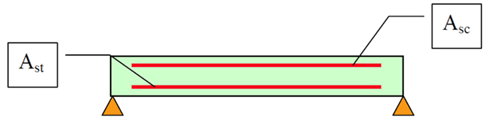
The area of the top and bottom steel reinforcement must be adequate such that the negative and positive bending moments does not exceed the capacity of the slab, $ϕM_u$.
$A_{st}$ (area of tensile reinforcement) is unknown, so the moment capacity, $ϕM_u$ , can be equated to the bending moment structural action ($M*$) in order to solve the equation for $A_{st}$ and $p$ (reinforcement ratio = $A_{st}/(bd))$. We can substitute $A_{st}=pbd$ into the bending moment capacity equation.
$$\phi Mu= \phi A_{st}f_{sy}d(1-\frac{pf_{sy}}{1.7f_c’})$$
$$M*(10^6)=0.8§(1000)(270)(400)(270)(1-\frac {p(400)}{1.7(32)}) \to p=0.13483$$
Each of the above cases for p were compared to the minimum reinforcement value, $p_{min}$.
$p_{min}=0.2(\frac {D^2}{d})(\frac {f’{cf}}{f{sy}})=0.0021 \text{where} f’_{cf}=0.6\sqrt{f’c}$
Comparing the $p$ derived from solving the capacity equation against the $p_{min}$ value, the higher value was found to be $p$ for all cases and thus will be the value used to calculate the final required area of steel reinforcement, $A_{st}$.
$$A_{st}=pbd=0.134831000270=36,404mm^2$$
To achieve this area of steel, 12 No. N32 bars will be spaced along the bottom per meter of the slab to provide a sufficient reinforcement area of 38,584.32.
$\phi M_u=0.838584.32400270(1-\frac {0.13483400}{1.732})=27,944,126Nmm=27.9kNm$
$$\mathrm{M}_{MAX}^{*} =27kNm \lt Mu \to \text{Slab is safe for strength}$$
Serviceability Limit State Design
For one-way slabs, serviceability design can be checked as per AS3600:2018 Clause 9.4.4.1.
$K_{cs}$ is determined per AS 3600:2018 Clause 8.5.3.2, where $A_{sc}$ is the area of steel in the top reinforcement (compression), and $A_{st}$ is the area of steel in the bottom reinforcement (tension).
$$k_{cs}=(2-1.2(\frac {A_{sc}}{A_{st}})) \ge 0.8$$
The below table displays the parameters that were utilised to check the serviceability equations.
We then substitute these parameters into the deemed to comply deflection equation to determine if the slab is satisfactory for serviceability.
$$\frac {L_{ef}}{d}=k_3k_4((\frac {\frac {\Delta}{L_{ef}}E_c}{F_{d.ef}})^\frac {1}{3}$$
These factors give $\frac {L_{ef}}{d} = 2.30559$
As the depth of the slab was used as 300mm, as given in Appendix D.1, the span of 4000mm gives a span-to-depth ratio of 13.33. As $\frac {L_{ef}}{d}$ is less than the span-to-depth ratio, the one-way spanning slab is safe for serviceability.
Slab Design to AS 3600 using ClearCalcs
ClearCalcs is a tool that can help engineers save a lot of time when designing slabs. It can also reduce material costs by providing instant feedback on the structural utilization of the slab as soon as changes are made to the parameters.
This way, engineers can produce the most structurally efficient design while saving time and reducing costs.
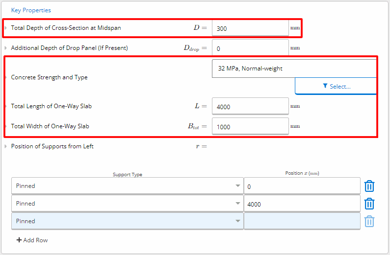
Inputting Key Properties
To begin, we can input the relevant details and loads for the 32MPa, simply supported slab that is 300mm thick and has a width of 1 meter. This is for an office building that features columns spaced 4m vertically and 8m horizontally in plan view.
The key parameters of the slab are summarised below.
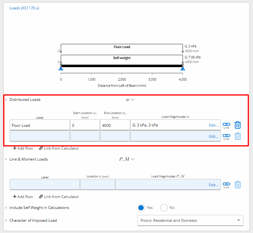
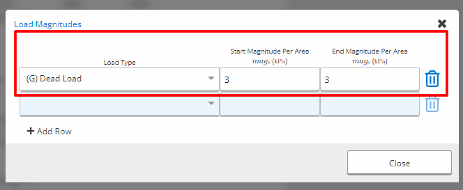
Inputting Loads
Given that we are designing the slab for uniformly distributed imposed action of 3.0kPa, we can input the loads to the Distributed Loads section.
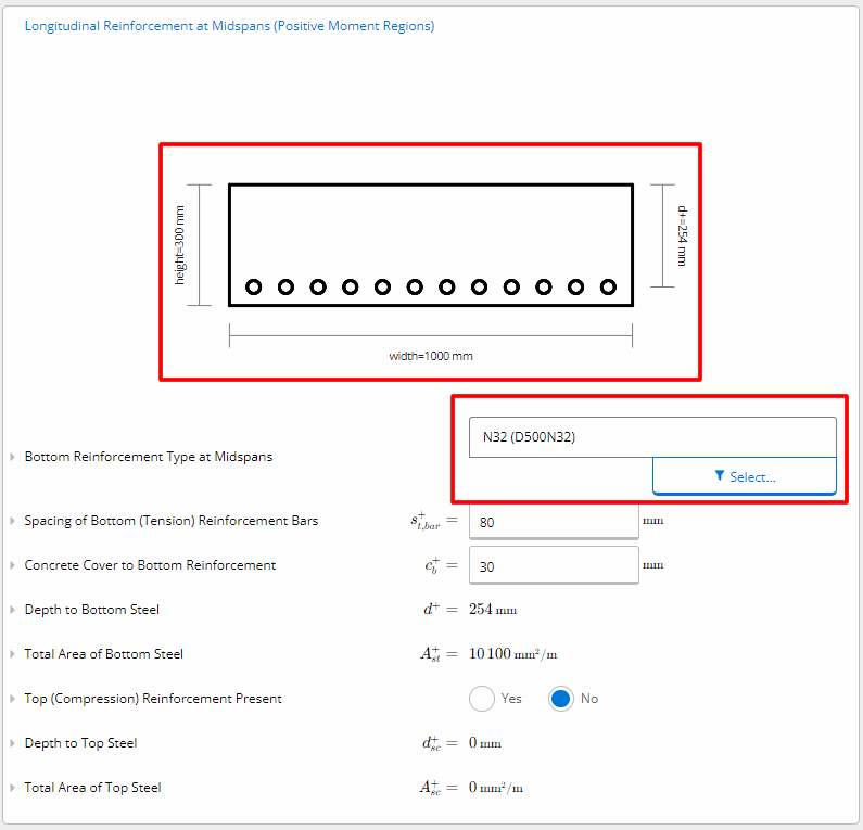
Reinforcement Details
By inputting the 12 No. N32’s into the Longitudinal Reinforcement at Midspans (Positive Moment Regions) field we get a compliant slab.
However, ClearCalcs can allow us to try different reinforcement arrangements with instant feedback. Let’s input the spacing between the bars as 200mm, so only 5 bars are used.
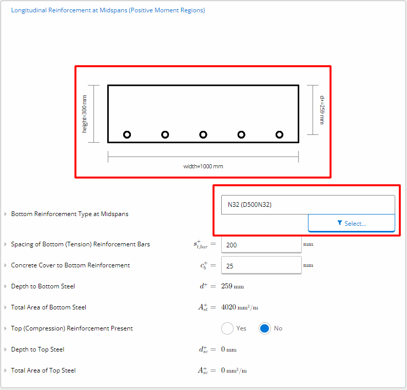
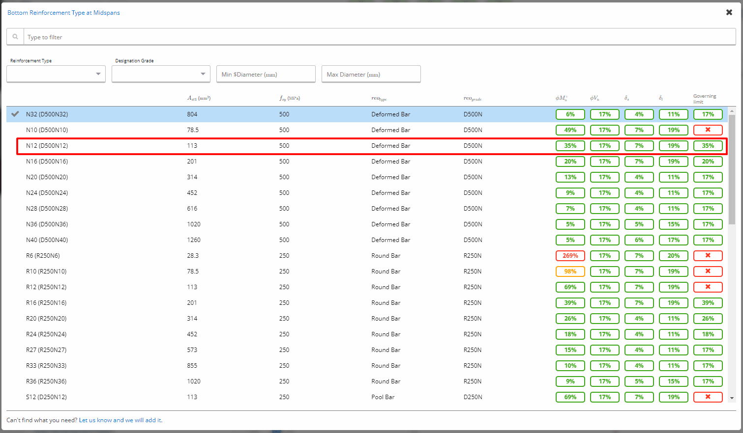
We can then use the reinforcement selector that checks moment, shear, and deflection instantaneously to determine that N12 is an adequate size rebar for this reinforcement arrangement.
This instant feedback enables engineers to optimize designs, reducing steel costs and helping the project’s budget and the environment.
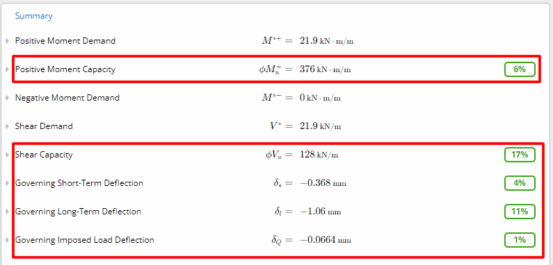
Summary
We can view the concrete slab’s utilization in the Summary section. This includes the following governing checks:
- Positive and Negative Moment Demand: Design bending moment applied to the section based on the selected Load Case of design.
- Positive Moment Capacity: Factored positive moment capacity at midspans.
- Shear Demand: Design shear force applied in the section due to applied loads.
- Shear Capacity: Factored shear capacity
- Governing Deflection: Taken as the governing deflection (upward or downward) anywhere along the beam. This is the deflection with the largest utilization ratio. Negative deflections are downward deflections, while positive deflections are upward deflections
Conclusion
Designing reinforced concrete slabs is crucial for design and construction professionals in Australia. This article provides a guide to understanding slab types, applications, and the design process in accordance with Australian Standard AS 3600.
We cover load calculations, reinforcement detailing, temporary works, construction joints, and hand calculations for slab design.
ClearCalcs offers a solution that saves time and optimizes material use for cost savings and environmental sustainability. It provides instant feedback on structural utilization to make informed decisions quickly and confidently.
Ready to start calculating in ClearCalcs?
You can use the account for 14 days for free, with no commitment required. Need ClearCalcs for a one-off project? Subscribe to our month-to-month plan and cancel anytime, no questions asked.
Seismic Retrofit Series: URM Insights for US and Canada Engineers
August 5th at 1 pm Eastern Time (ET)
Save your spot →Written by:

Kyle Conway
.svg)
Reviewed by:


.png)
