

Reinforced concrete beams are used in structures where a horizontal load path is required. They typically support floor elements (usually concrete slabs) but can be used in a range of applications.
This article will explore the use cases and advantages of reinforced concrete beams in concrete design. We'll also provide an overview of the relevant design standard in Australia (AS 3600:2018), highlight its changes from previous versions, and discuss fundamental principles, calculations, and methods for reinforced concrete design to achieve both strength and serviceability.
Additionally, we'll provide some tips on best practices for design, formwork, construction, and quality assurance.
Table of Contents:
- What are Rectangular Concrete Reinforced Beams?
- Overview of AS 3600:2018 Concrete Structures
- Rectangular Concrete Reinforced Beams Design
- Beam Design Process and Calculation Methods
- Reinforced Concrete Beam Design Example
- Best Practices for Concrete Beam Design
- Reinforced Concrete Beam Construction
What are Rectangular Concrete Reinforced Beams?
Reinforced concrete beams are constructed from a combination of both concrete and steel.
- Concrete is brittle and weak in tension while strong in compression
- Steel is ductile and is used in reinforced concrete to carry tension
Figure 1: Example of reinforced concrete beams (Reference)
The part of a structure that has a tensile force acting on it is called a Tie, and the part that has a compressive force acting on it is called a Strut. Concrete naturally acts as a Strut.
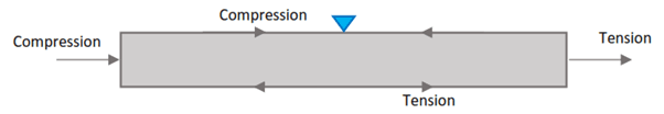
Figure 2: Illustration of forces acting on reinforced concrete beams
The steel reinforcement provides all the tensile strength where concrete is in compression, and the two materials act together in resisting forces. Reinforced concrete beams are used where the loads/spans are too great to use timber or steel beams, and a stronger and larger section size is required.
The following are some of the benefits of using reinforced concrete in construction:
- Ability to resist high-stress environments
- Durability and sturdiness
- Resistance to fire and weathering
- Low maintenance requirements
Reinforced concrete beams are widely used in the construction of buildings, highways, roads, traffic, precast structures, floating structures, Hydro-power tunnels, irrigation canals, and drains, among other conceivable structures.
Overview of AS 3600:2018 Concrete Structures
Australian standard AS 3600:2018 provides guidelines for designing and constructing concrete structures in Australia.
The scope of the standard includes the design of reinforced and prestressed concrete structures, including beams, columns, walls, slabs, and footings. The standard also covers the design of concrete structures subjected to fire, earthquake, and wind loads.
The changes from the previous version of the standard include:
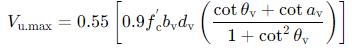
- Upper limit shear strength ( V u . m a x V_{u.max} Vu.max) has been reduced by 10% in equation 8.2.3.3(1).
- Factor k v kv kv (simplified method) increases the concrete shear capacity ( V u c V_{uc} Vuc).
- Increase of 33% to minimum area of shear reinforcement.
- Modified alpha2 (MCFT) approach derived from the Canadian code approach CSA A23.3.
- Increase to the capacity reduction factors ( ø ø ø factors) in Table 2.2.2.
The changes aim to address issues in beam design for shear and torsion, increase the capacity reduction factors, and improve the calculation of shear capacity.
The Concrete Institute of Australia presented a symposium titled “The New AS3600-2018 Concrete Structures Code – What Impact Will It Have On You?” to discuss the changes and their impact on structural design for slabs, beams, and walls from previous versions.
Rectangular Concrete Reinforced Beams Design
The fundamental design principles specified in AS 3600 for reinforced concrete beams include the following:
- Load and Load Combinations: Determine the loads and load combinations that the beam will be subjected to, including dead loads, live loads, wind loads, and earthquake loads.
- Section Properties: Calculate the section properties of the beam, including the area, moment of inertia, and section modulus.
- Bending Moment Capacity: Calculate the bending moment capacity of the beam using the appropriate equations and charts in AS 3600.
- Shear Capacity: Calculate the shear capacity of the beam using the appropriate equations and charts in AS 3600.
- Reinforcement: Determine the reinforcement required to resist the bending moment and shear force, including the size, spacing, and placement of the reinforcement.
- Formwork Design: Design the formwork for the beam to ensure that it is safe and complies with AS 3610 Formwork for Concrete.
- Quality Assurance: Implement quality assurance measures to ensure that the finished product meets the required standards and specifications.
- Strut-and-Tie Design Method: AS 3600 includes a new chapter covering the strut-and-tie design method to reflect the new section in AS 3600.
- Design for Durability: AS 3600 includes provisions for designing reinforced concrete structures for durability, including exposure classes and minimum cover requirements.
- Serviceability Limit State: AS 3600 includes provisions for designing reinforced concrete structures to meet serviceability limit state requirements, including deflection and cracking.
Beam Design Process and Calculation Methods
1. Structural Actions: Simplified Method of Analysis of Continuous Beams
The first step in the design of a reinforced concrete beam is determining the structural actions.
The load combinations for strength and serviceability design can be found in AS 1170.0 Section 4.
Strength Design: 𝐹 d = 1.2 ∗ 𝐺 + 1.5 ∗ 𝑄 𝐹d = 1.2 ∗ 𝐺 + 1.5 ∗ 𝑄 Fd=1.2∗G+1.5∗Q
Note: When computing Uniformly Distributed Loads (UDL’s), use the span-to-span length.
Serviceability Design: Long-Term: 𝐺 + 𝜓 𝑙 ∗ 𝑄 𝐺 + 𝜓𝑙 * 𝑄 G+𝜓l∗Q Short-Term: 𝐺 + 𝜓 𝑠 ∗ 𝑄 𝐺 + 𝜓𝑠 *𝑄 G+𝜓s∗Q
Dead Load ( G G G): Weight of structure itself and any installed equipment Live Load ( Q Q Q): Loads for various uses and occupancies
AS 3600 Clause 6.10.2.2 to 6.10.2.4 may be used for the calculation of design bending moments and shear forces for strength in continuous beams and one-way spanning slabs of reinforced concrete construction (note: 𝐹 𝑑 𝐹𝑑 Fd = uniformly distributed load per unit length factored for strength).
Figure 3 & Figure 4 diagrammatically demonstrate the appropriate coefficients to multiply by ( F d ∗ L n 2 Fd*Ln^2 Fd∗Ln2) to determine the moment action in the beam using the simplified method.
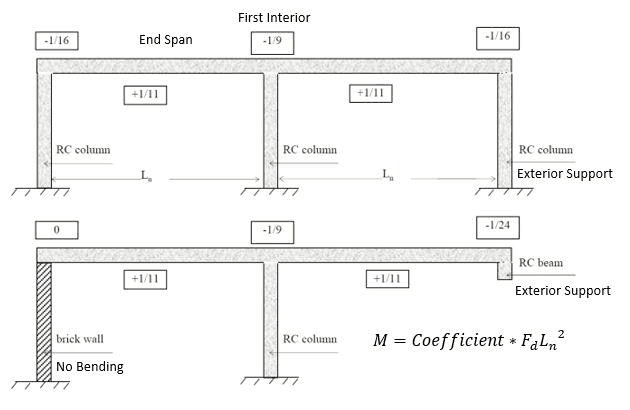
Figure 3: Simplified Method Coefficients for Two Spans
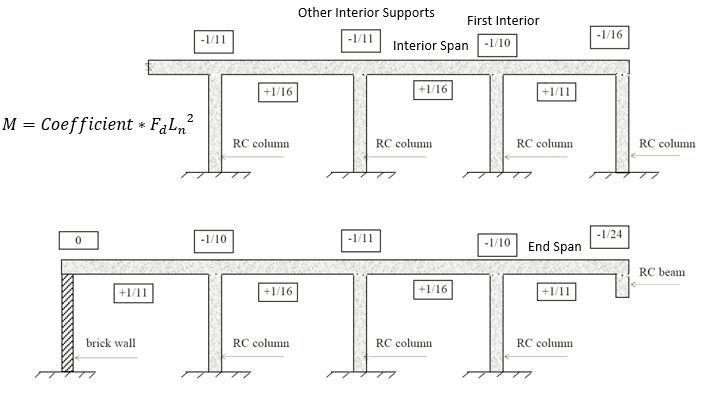
Figure 4: Simplified Method Coefficients for Multiple Spans
2. Moment Capacity: Reinforced Concrete Beam
Next the structural capacity for strength needs to be determined. Let’s start by checking the moment capacity of a reinforced concrete beam. The design of beams for strength and serviceability is covered in AS 3600:2018 Section 8.
There are two scenarios that occur when determining the moment capacity of a reinforced concrete beam.
Scenario 1. Calculate the design force/moment for a given reinfoced concrete section where the reinforcement area of the cross section ( A s t Ast Ast) is known which is quite easy following the below steps;
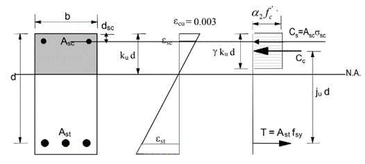
- Use force equilibrium (Compression=Tension) across the rectangular stress block detailed in AS 3600:2018 Section 8.1.2 (shown below) to solve for the neutral axis parameter ( k u k_u ku).
- Then solve for the moment capacity ( M u M_u Mu) with known neutral axis parameter ( k u k_u ku).
- This procedure is shown in more detail in Section 3.2.1.
Scenario 2. Calculate the beam size and amount of steel reinforcement (Ast) for a given design moment (structural action) where ( A s t A_{st} Ast is unknown) which is more difficult and follows the below steps.
- Use force equilibrium (Compression=Tension) across the rectangular stress block to develop the below two equations
- Solve simultaneously for the neutral axis parameter ( k u k_u ku) and the required reinforcement area of the cross section ( A s t A_{st} Ast)
- A worked example of this procedure is shown in this article.
Moment Capacity of a Reinforced Concrete Beam with known dimensions and reinforcement
By Force Equilibrium we can deduce:
∑ 𝐹 𝑥 = 0 ∑ 𝐹𝑥 = 0 ∑Fx=0
𝐶 𝑐 + 𝐶 𝑠 = 𝑇 𝐶𝑐 + 𝐶𝑠 = 𝑇 Cc+Cs=T
𝛼 2 ∗ 𝑓 ′ 𝑐 ∗ ( 𝛾 ∗ 𝑘 𝑢 ∗ 𝑑 ∗ 𝑏 ) + ( 𝐴 𝑠 𝑐 ∗ 𝜎 𝑠 𝑐 ) = ( 𝐴 𝑠 𝑡 ∗ 𝑓 𝑠 𝑦 ) 𝛼2 * 𝑓′𝑐 * (𝛾 * 𝑘𝑢 * 𝑑 ∗ 𝑏) + (𝐴𝑠𝑐 * 𝜎𝑠𝑐) = (𝐴𝑠𝑡 * 𝑓𝑠𝑦) 𝛼2∗f′c∗(𝛾∗ku∗d∗b)+(Asc∗𝜎sc)=(Ast∗fsy)
Assuming 𝜎 𝑠 𝑐 = 𝑓 𝑠 𝑦 𝜎𝑠𝑐 = 𝑓𝑠𝑦 𝜎sc=fsy, then we can solve for the neutral axis parameter ( k u k_u ku).
Note the main assumption is positive bending (beam sagging) (with the compressive reinforcement ( A s c A_{sc} Asc) on top and tensile reinforcement ( A s t A_{st} Ast) on bottom). However, if it is a negative bending moment (beam hogging) these should be switched.
Note: Always assume tension side has yielded (hence the fsy). However, we do not know if compression side has yielded so we need to do a check.
As per the requirements of AS 3600:2018 Section 8.1.3 the maximum strain in the extreme compressive fibre ( ε c u ε_{cu} εcu) is 0.003.
Using this we can check our assumption for 𝜎 𝑠 𝑐 𝜎𝑠𝑐 𝜎sc using the strain diagram below:
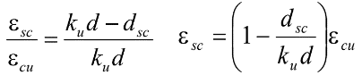
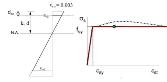
If ε s c > ε s y = f s y / E s εsc > εsy = fsy / E_s εsc>εsy=fsy/Es, then the assumption 𝜎 𝑠 𝑐 = 𝑓 𝑠 𝑦 𝜎𝑠𝑐 = 𝑓𝑠𝑦 𝜎sc=fsyis correct and the moment capacity as determined by force equilibrium is shown below.
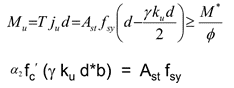
M u = ( 𝛼 2 ∗ 𝑓 ′ 𝑐 ∗ 𝛾 ∗ 𝑘 𝑢 ∗ 𝑑 ∗ 𝑏 ) ∗ ( 𝑑 – ( ( 𝛾 ∗ 𝑘 𝑢 ∗ 𝑑 ) / 2 ) ) + ( ( 𝐴 𝑠 𝑐 ∗ 𝑓 𝑠 𝑦 ) ∗ ( 𝑑 − 𝑑 𝑠 𝑐 ) ) Mu = (𝛼2 * 𝑓′𝑐 * 𝛾 * 𝑘𝑢 * 𝑑 ∗ 𝑏) * (𝑑 – ((𝛾 * 𝑘𝑢 * 𝑑)/2)) + ((𝐴𝑠𝑐 * 𝑓𝑠𝑦) * (𝑑 − 𝑑𝑠𝑐)) Mu=(𝛼2∗f′c∗𝛾∗ku∗d∗b)∗(d–((𝛾∗ku∗d)/2))+((Asc∗fsy)∗(d−dsc))
If 𝜀 𝑠 𝑐 < 𝜀 𝑠 𝑦 , 𝜎 𝑠 𝑐 < 𝑓 𝑠 𝑦 𝜀𝑠𝑐 < 𝜀𝑠𝑦, 𝜎𝑠𝑐 < 𝑓𝑠𝑦 𝜀sc<𝜀sy,𝜎sc<fsy, then a recalculation of k u k_u ku and σ s c σsc σsc is Required:
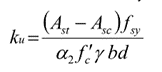
By force equilibrium above we deduced: 𝛼 2 ∗ 𝑓 ′ 𝑐 ∗ ( 𝛾 ∗ 𝑘 𝑢 ∗ 𝑑 ∗ 𝑏 ) + ( 𝐴 𝑠 𝑐 ∗ 𝜎 𝑠 𝑐 ) = ( 𝐴 𝑠 𝑡 ∗ 𝑓 𝑠 𝑦 ) 𝛼2 * 𝑓′𝑐 * (𝛾 * 𝑘𝑢 * 𝑑 ∗ 𝑏) + (𝐴𝑠𝑐 * 𝜎𝑠𝑐) = (𝐴𝑠𝑡 * 𝑓𝑠𝑦) 𝛼2∗f′c∗(𝛾∗ku∗d∗b)+(Asc∗𝜎sc)=(Ast∗fsy)
We can substitute in, 𝜎 𝑠 𝑐 = 𝐸 𝑠 ∗ 𝜀 𝑠 𝑐 = 𝐸 𝑠 ∗ 𝜀 𝑐 𝑢 ( 1 – ( 𝑑 𝑠 𝑐 / ( 𝑘 𝑢 ∗ 𝑑 ) ) ) 𝜎𝑠𝑐 = 𝐸𝑠 * 𝜀𝑠𝑐 = 𝐸𝑠 * 𝜀𝑐𝑢 (1 – (𝑑𝑠𝑐/(𝑘𝑢 * 𝑑))) 𝜎sc=Es∗𝜀sc=Es∗𝜀cu(1–(dsc/(ku∗d)))
To give, 𝛼 2 ∗ 𝑓 ′ 𝑐 ∗ ( 𝛾 ∗ 𝑘 𝑢 ∗ 𝑑 ∗ 𝑏 ) + 𝐴 𝑠 𝑐 [ 𝐸 𝑠 ∗ 𝜀 𝑐 𝑢 ∗ ( 1 − ( 𝑑 𝑠 𝑐 / ( 𝑘 𝑢 ∗ 𝑑 ) ) ] = 𝐴 𝑠 𝑡 ∗ 𝑓 𝑠 𝑦 𝛼2 * 𝑓′𝑐 * (𝛾 * 𝑘𝑢 * 𝑑 ∗ 𝑏) + 𝐴𝑠𝑐 [𝐸𝑠 * 𝜀𝑐𝑢 * (1 - (𝑑𝑠𝑐 / (𝑘𝑢 * 𝑑))] = 𝐴𝑠𝑡 * 𝑓𝑠𝑦 𝛼2∗f′c∗(𝛾∗ku∗d∗b)+Asc[Es∗𝜀cu∗(1−(dsc/(ku∗d))]=Ast∗fsy
The above equation can be solved for the neutral axis parameter (ku), and then we can calculate, 𝜎 𝑠 𝑐 = 𝐸 𝑠 ∗ 𝜀 𝑠 𝑐 = 𝐸 𝑠 ∗ 𝜀 𝑐 𝑢 ( 1 – ( 𝑑 𝑠 𝑐 / ( 𝑘 𝑢 ∗ 𝑑 ) ) ) 𝜎𝑠𝑐 = 𝐸𝑠 * 𝜀𝑠𝑐 = 𝐸𝑠 * 𝜀𝑐𝑢 (1 – (𝑑𝑠𝑐/(𝑘𝑢 * 𝑑))) 𝜎sc=Es∗𝜀sc=Es∗𝜀cu(1–(dsc/(ku∗d))) which gives the moment capacity as below.
M u = ( 𝛼 2 ∗ 𝑓 ′ 𝑐 ∗ 𝛾 ∗ 𝑘 𝑢 ∗ 𝑑 ∗ 𝑏 ) ∗ ( 𝑑 – ( ( 𝛾 ∗ 𝑘 𝑢 ∗ 𝑑 ) / 2 ) ) + ( ( 𝐴 𝑠 𝑐 ∗ 𝜎 𝑠 𝑐 ) ∗ ( 𝑑 − 𝑑 𝑠 𝑐 ) ) Mu = (𝛼2 * 𝑓′𝑐 * 𝛾 * 𝑘𝑢 * 𝑑 ∗ 𝑏) * (𝑑 – ((𝛾 * 𝑘𝑢 * 𝑑)/2)) + ((𝐴𝑠𝑐 * 𝜎𝑠𝑐) * (𝑑 − 𝑑𝑠𝑐)) Mu=(𝛼2∗f′c∗𝛾∗ku∗d∗b)∗(d–((𝛾∗ku∗d)/2))+((Asc∗𝜎sc)∗(d−dsc))
3. Shear Capacity: Reinforced Concrete Beams
The steps to determine the shear capacity of a reinforced concrete beam are below.
Step 1: Determine the Maximum Ultimate Shear Strength ( V u , m a x V_{u,max} Vu,max) in accordance with AS 3600:2018 Section 8.2.3.3.
Take 𝛼 𝑣 = 90 𝛼𝑣 = 90 𝛼v=90 and 𝜃 𝑣 = 36 𝜃𝑣 = 36 𝜃v=36.
Note: If V ∗ V* V∗ (determined in Section 3.1) > φ V u . m a x > φV_{u.max} >φVu.max then increase the dimensions of the beam.
Step 2: Transverse Shear Reinforcement (Vus) shall be provided in regions where 𝑉 ∗ > 𝜙 ( 𝑉 𝑢 𝑐 ) , T ∗ > 0.25 𝜙 T c r 𝑉∗ > 𝜙(𝑉𝑢𝑐), T* > 0.25𝜙Tcr V∗>𝜙(Vuc),T∗>0.25𝜙Tcr, or if the depth of the member is greater than 750mm
Where 𝜙 = 0.75 , 𝑉 ∗ = 1.2 𝐺 + 1.5 𝑄 𝜙 = 0.75, 𝑉* = 1.2𝐺 + 1.5𝑄 𝜙=0.75,V∗=1.2G+1.5Q (determined in Section 3.1) 𝑉 𝑢 𝑐 = k v ∗ b v ∗ d v ∗ s q r t ( f ’ c ) 𝑉𝑢𝑐 = kv * bv * dv * sqrt(f’c) Vuc=kv∗bv∗dv∗sqrt(f’c) in accordance with AS 3600:2018 Section 8.2.4 𝜙 V u s = V ∗ − 𝜙 V u c 𝜙Vus = V* - 𝜙Vuc 𝜙Vus=V∗−𝜙Vuc
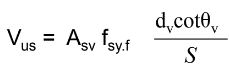
As per AS 3600:2018 Section 8.2.5, the area of transverse reinforcement ( A s v A_{sv} Asv) and stirrup spacing ( S S S) can then be determined by iterating the below equation.
Step 3: If 𝑉 ∗ < 𝜙 𝑉 𝑢 𝑐 𝑉*< 𝜙𝑉𝑢𝑐 V∗<𝜙Vuc but the Overall Depth of Member D D D ≥ 750 mm, provide minimum transverse reinforcement area ( A s v A_{sv} Asv)
4. Serviceability Check for RC Beams
Deflection Modes:
- Short-Term Deflections: Instant deflection caused by loads
- Long-Term Deflection: Additional sustained-load deflection by creep
As per AS 3600:2018 Section 8.5.3.1:
Short-Term Deflection at Mid-Span (Simply Supported Beam):
∆ 𝑠 = ( 5 ∗ 𝑤 𝑠 ∗ 𝐿 𝑒 𝑓 4 ) / ( 384 ∗ 𝐸 ∗ 𝐼 𝑒 𝑓 ) ∆𝑠 = (5 ∗ 𝑤𝑠 ∗ 𝐿𝑒𝑓^4)/(384 ∗ 𝐸 ∗ 𝐼𝑒𝑓) ∆s=(5∗ws∗Lef4)/(384∗E∗Ief)
Short-Term Deflection at Mid-Span (Continuous Beam):
∆ 𝑠 = ( ( 5 ∗ 𝑤 𝑠 ∗ 𝐿 𝑒 𝑓 2 ) / ( 48 ∗ 𝐸 𝑐 ∗ 𝐼 𝑒 𝑓 ) ) ∗ [ 𝑀 𝑚 − 0.1 ( 𝑀 𝑎 + 𝑀 𝑏 ) ] ∆𝑠 = ((5 ∗ 𝑤𝑠 ∗ 𝐿𝑒𝑓^2)/ (48 ∗ 𝐸𝑐 ∗ 𝐼𝑒𝑓)) * [𝑀𝑚 − 0.1(𝑀𝑎 + 𝑀𝑏)] ∆s=((5∗ws∗Lef2)/(48∗Ec∗Ief))∗[Mm−0.1(Ma+Mb)]
Where: w s ws ws = uniformly distributed service load, 𝐿 𝑒 𝑓 𝐿𝑒𝑓 Lef = effective length, E E E = modulus of elasticity, I e f Ief Ief=effective second moment of area, M m Mm Mm=midspan moment, M a Ma Ma=moment at support A A A, M b Mb Mb = moment at support B B B.
As per AS 3600:2018 Section 8.5.3.2:
Long-Term Deflection:
∆ l = ∆ 𝑠 ∗ k c s ∆l=∆𝑠*kcs ∆l=∆s∗kcs
Where: k c s kcs kcs = factor used in serviceability design to take account of the long-term effects of creep and shrinkage.
Reinforced Concrete Beam Design Example
Reinforced Concrete Beam Design by Hand Calculation
Example:
For a singly reinforced simply supported rectangular section with:
- width (b)=250 mm
- depth to tensile reinforcement from top of beam (d)=500 mm
- total beam depth (D)=575 mm
- concrete compressive strength of (f’c) =50 MPa
- Class N reinforcement (fsy=500 MPa)
Determine the amount of reinforcement required when a 6000mm interior span beam is subjected to a uniformly distributed dead load of 10kN/m. Consider moment as the critical loading.
As per part 3.1 of this article, the load combinations for strength and serviceability design can be found in AS 1170.0 Section 4.
Strength Design: 𝐹 d = 1.2 ∗ 𝐺 + 1.5 ∗ 𝑄 = 1.2 ∗ 10 k N / m = 12 k N / m 𝐹d = 1.2 ∗ 𝐺 + 1.5 ∗ 𝑄 = 1.2*10kN/m= 12kN/m Fd=1.2∗G+1.5∗Q=1.2∗10kN/m=12kN/m
For a simply supported beam: M ∗ = F d ∗ ( L 2 ) / 8 = 12 ∗ ( 6 2 ) / 8 = 54 k N m M* = Fd*(L^2)/8 = 12*(6^2)/8 = 54kNm M∗=Fd∗(L2)/8=12∗(62)/8=54kNm
As we have a given design moment (structural action) where (Ast is unknown) which should follow the below steps as per Case 2 in Section 3.2.
Step 1: Use force equilibrium (Compression=Tension) across the rectangular stress block to develop the below two equations
Step 2: Solve simultaneously for the neutral axis parameter (ku) and the required reinforcement area of the cross section (Ast)
fsy=500MPa, d=500mm, b=250mm, f’c=50MPa, capacity reduction factor = 0.85 as per AS 3600:2018 Table 2.2.2
As per AS 3600:2018 Section 8.1.3: 𝛾=0.97-(0.0025*f’c)>0.67=0.845, 𝛼2=0.85-0.0015f’c>0.67=0.775
By solving the above two equations simultaneously we yield: ku=0.0499, Ast=402mm^2
We can use 2 N16 bars as bottom tensile reinforcement to achieve the 402mm^2 required area of tensile reinforcement.
Note: Shear should be checked as per Section 3.3 of this article and deflection should be checked as per Section 3.4 of this article. It is always imperative to verify hand calculations using software.
Reinforced Concrete Beam Design by ClearCalcs
Using ClearCalcs Concrete Beam Calculator to AS 3600:2018, we can greatly speed up the design process and even improve a conforming design to be more structurally efficient.
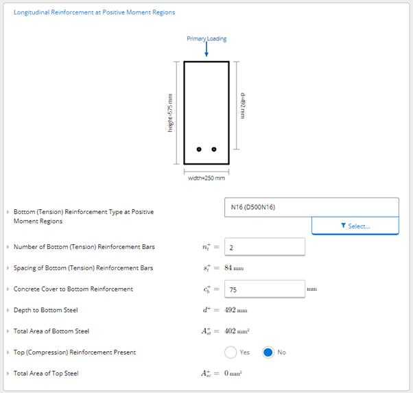
First, we input the key properties of the problem as per the below.
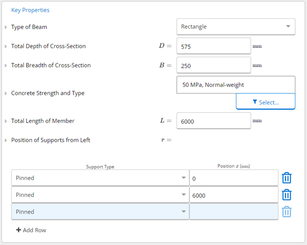

Based on these inputs, we can check the structural adequacy of the tensile reinforcement being 2 N16 bars using the traffic light checks for moment, shear and deflection utilisation of the beam.
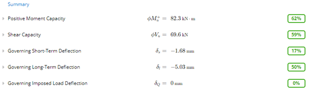
We can see that the design is conforming, but at only 62% utilisation, we could seek to make the design even more efficient, by reducing the beam size or reinforcement area to save money during construction or we could achieve a longer span for the beam which may be more architecturally pleasing.
ClearCalcs provides instantaneous feedback to any changes made to the inputs rather than having to perform all the calculations again!
Best Practices for Concrete Beam Design
Ensure Failure is Ductile
Concrete beams can be under-reinforced, over-reinforced, or balanced-reinforced, depending on the design criteria which determines the failure mechanism.
To ensure a gradual ductile failure (which will show signs of fatigue and allow occupants to safely leave the building before failure), the beam must be under-reinforced.
This can be satisfied by setting a limit on the depth of neutral axis factor ( k u k_u ku) to be less than that corresponding to a balanced failure state: k u k_u ku < k u b k_{ub} kub. According to AS 3600, k u k_u ku < 0.36. This will result in an adequate ductility provided in the beam. Over-reinforced beams where k u k_u ku > k u b k_{ub} kub can experience brittle failure that results in instantaneous collapse.
Note: Satisfying 𝑘𝑢 ≤ 0.36 is equivalent to 𝑝 ≤ 𝑝𝑚𝑎𝑥 where p is the reinforcement ratio.
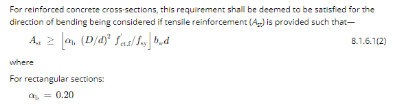
Minimum Amount of Flexural Reinforcement:
There are minimum strength requirements in AS 3600:2018 Section 8.1.6 that denote the minimum amount of flexural reinforcement that must be checked during the design (excerpt below).
Crack Control of Beams
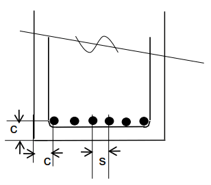
Crack control of beams is covered in AS 3600:2018 Section 8.6. Some key steps are summarised below.
Step 1: Check Concrete Cover and Bar Spacing: Cover<100mm & >40mm, Spacing<300mm
Step 2: Check Tension Stress in Bars
Using the moment capacity in service of the reinforcement.
𝑀 𝑠 = 𝑇 𝑗 𝑑 = 𝐴 𝑠 𝑡 𝑓 𝑠 𝑡 𝑗 𝑑 𝑀𝑠 = 𝑇𝑗𝑑 = 𝐴𝑠𝑡𝑓𝑠𝑡𝑗𝑑 Ms=Tjd=Astfstjd
Assume: 𝑗 ≈ 0.9 𝑗 ≈ 0.9 j≈0.9
𝑓 𝑠 𝑡 = 𝑀 𝑠 / ( 𝐴 𝑠 𝑡 ∗ 𝑗 ∗ 𝑑 ) 𝑓𝑠𝑡 =𝑀𝑠/(𝐴𝑠𝑡*𝑗*𝑑) fst=Ms/(Ast∗j∗d) < 𝑀𝑎𝑥𝑖𝑚𝑢𝑚 𝑆𝑡𝑟𝑒𝑠𝑠 where, $𝑀𝑠 = 𝐺 + 0.7𝑄$$
Check against the Tables in AS 3600:2018 Section 8.6.2.2
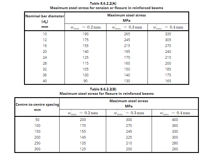
Table 8.6.2.2 in AS 3600:2018 for maximum steel stress for tension or flexure in reinforced beams
Detailing of Reinforcement
AS 3600:2018 Section 8.3 details the requirements for detailing of reinforcement and should be referred to after calculating the amount of flexural and shear reinforcement.
Some of the key requirements for flexural reinforcement are summarised below.
For the negative bending force at supports:
- At least one quarter of the reinforcement should cover the entire span.
- More than half should extend at least 0.3 times the beam's length beyond the support.
- Any remaining reinforcement should extend at least 0.2 times the beam's length beyond the support.
Unequal spans:
- Extensions of negative reinforcement should consider the longer span's requirements.
For the positive bending force at midspan:
- At least half of the reinforcement should reach 12 times the bar diameter into a simple support.
- A quarter should reach into a support for continuous or flexurally restrained beams.
- Any remaining reinforcement should reach within 0.1 times the beam's length from the support.
Regarding shear requirements:
- Not more than a quarter of the maximum tensile reinforcement should end within 2 times the beam's depth.
These rules ensure proper placement and lengths of reinforcing bars to support the beams and meet necessary strength criteria. There are a range of detailing requirements for shear and torsional reinforcement in the standard that also need to be adhered to.
Reinforced Concrete Beam Construction
Formwork Design and Certification Requirements
- Formwork design should be safe and comply with AS 3610 Formwork for Concrete and AS 3600 Concrete Structures.
- A formwork designer or engineer is responsible for overseeing the safe design of the complete formwork structure, including the formwork support structure, the formwork deck, and connection details. They need to attend site for regular compliance inspections.
- Basic formwork systems may be certified by a formwork designer, while non-basic formwork systems require certification by an engineer.
Construction Practices
- Consideration should be made for if precast or in-situ reinforced concrete beams would be cheaper & faster to construct by weighing up crane & concrete truck cost access as well as the safety of construction workers.
- The concrete mix design should be appropriate for the intended use and should meet the requirements of AS3600 Concrete Structures.
- The reinforcement should be placed correctly and secured in place to ensure it does not move during the concrete pour.
- The concrete should be placed and compacted properly to ensure it fills all voids and achieves the required strength.
QA Requirements
- Quality assurance is important in reinforced concrete beam construction to ensure that the finished product meets the required standards and specifications.
- QA requirements include inspections and testing of the concrete mix, reinforcement, and finished product.
- QA requirements may also include documentation and record-keeping to ensure that all aspects of the construction process are properly documented and can be traced if necessary.
Ready to start calculating in ClearCalcs?
You can use the account for 14 days for free, with no commitment required. Need ClearCalcs for a one-off project? Subscribe to our month-to-month plan and cancel anytime, no questions asked.
Seismic Retrofit Series: URM Insights for US and Canada Engineers
August 5th at 1 pm Eastern Time (ET)
Save your spot →Written by:

Kyle Conway
.svg)
Reviewed by:


.png)
