

In concrete design, the development length of a reinforced concrete bar refers to the minimum length of the bar that needs to be embedded in concrete to ensure proper transfer of stresses between the reinforcing steel and the surrounding concrete.
What is development length of reinforced concrete bars?
When reinforcing bars (rebars) are used in concrete structures, they’re meant to provide tensile strength to the concrete. To effectively transfer this tensile force from the steel bar to the concrete, the bar needs to have enough length embedded within the concrete to develop its full strength.
Factors that influence the development length include:
- Bar Diameter: Thicker bars generally require a longer development length.
- Concrete Strength: Higher concrete strength might reduce the required development length.
- Bond Strength: Dependent on factors such as the surface condition of the bar, the quality of the concrete, and any additional mechanical means used to enhance bonding.
- Bar Position: If the bar is located near the surface or in congested areas of reinforcement, it might require additional development length.
Development length calculation to AS 3600:2018
For a reinforcement bar to reach its yield stress at a critical cross‐section, a minimum length of reinforcing bar (an anchorage) is required on either side of the section. It’s crucial to ensure the proper development length is provided to maintain structural integrity and prevent premature failure due to inadequate bonds between the concrete and reinforcement.
In Australia, AS 3600:2018 specifies a minimum length, called the development length, $L_{sy.t}$, over which a straight bar in tension must be embedded in the concrete in order to develop the yield stress.
$$L_{sy.t}\ge \frac {d_b}{4}*\frac {f_{sy}}{\phi f_b}$$
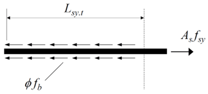
An average design ultimate bond stress $\phi f_b$ is assumed at the interface between the concrete and the reinforcing bar ($\phi = 0.6$).
$\phi f_b$ depends on:
- type and condition of reinforcing bar
- strength and compaction of concrete
- concrete cover
- bar spacing
- transverse reinforcement
- transverse pressure (or tension)
Basic Development Length
As per AS 3600:2018 (§13.1.2.2), The basic development length, $L_{sy.tb}$, is:
$$L_{sy.tb}= \ge \frac {0.5k_1k_3f_{sy}d_b}{k_2\sqrt{f’c}}\ge 0.058f{sy}k_1d_b$$
Where:
- Basic Development Length Coefficient, $k_1$ = 1.3 for a horizontal bar with > 300mm of concrete cast below it and $k_1$ = 1.0 for all other bars
- $k_2 = (132 – d_b)/100$
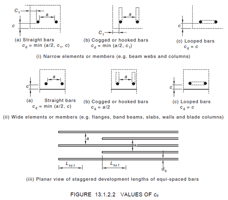
- $k_3 = 1.0 ‐ 0.15(c_d – d_b)/d_b (\text{but }0.7≤ k_3 ≤1.0)$
- $c_d$ is the smaller of the concrete cover to the bar or half the clear distance to the next parallel bar as per Figure 13.1.2.2
- $d_b$ is the bar diameter in mm
- Characteristic Compressive Strength, $f′_c$ shall not be taken to exceed 65 MPa
The value of $L_{sy.tb}$ calculated as above shall be:
a. multiplied by 1.5 for epoxy-coated bars; and
b. multiplied by 1.3 when lightweight concrete is used.
Refined Development Length
The development length Lsy.t may be taken as the basic development length or may be refined as per AS 3600:2018 Clause 13.1.2.3 to include the beneficial effects of confinements by transverse steel or transverse pressure and is given by:
$$L_{sy.t}=k_4k_5L_{sy.tb}$$
Where:
- $k_4$ = $1 ‐ Kλ$ (but 0.7≤ $k_4$ ≤ 1.0); where
- $λ = (ΣAtr − ΣAtr.min)/As$;
- $ΣAtr$ = cross-sectional area of the transverse reinforcement along the development length $L_{sy.t}$
- $ΣAtr.min$ = cross-sectional area of the minimum transverse reinforcement, which may be taken as 0.25$A_s$ for beams and 0 for slabs
- $A_s$ = cross-sectional area of a single bar of diameter $d_b$ being anchored
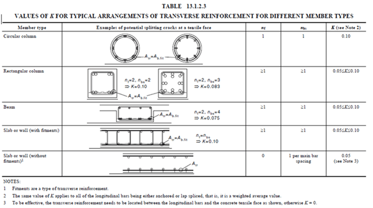
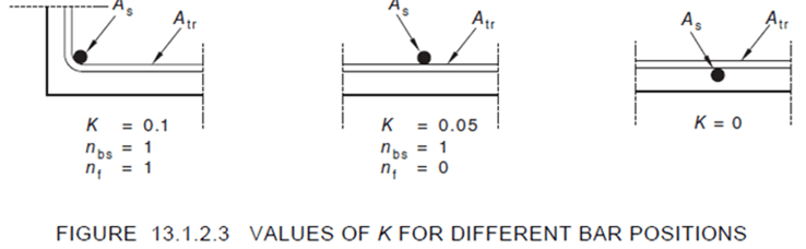
- $K$ = is a factor that accounts for the position of the bars being anchored relative to the transverse reinforcement, with values given below:
- $k_5 = 1.0 ‐ 0.04ρp (but 0.7≤ k_5 ≤1.0); where$
- $ρp$ is the transverse compressive pressure (in MPa), at the ultimate limit state along the development length and perpendicular to the plane of splitting
Development Length for Tensile Stress Lower than Yield Stress
Clause 13.1.2.4 addresses cases when the development length is only required to develop less than the yield strength. Where the full yield strength of the bar is not required, the development length ($L_{st}$) to develop a tensile stress ($\sigma _{st}$), less than the yield strength ($f_sy$), shall be calculated from:
$$L_{st}=L_{sy.t} \frac {\sigma_st}{f_{sy}}\ge 12d_b$$
When calculating ${\sigma_st}$, don’t forget to include the strength reduction factor ($φ = 0.8$). If $T*$ is the design ultimate tensile force in the reinforcement caused by the factored design loads, then:
$$T* \le \phi \sigma_{st}A_{st} \text{ which gives } \sigma_{st} \ge \frac {T*}{A_{st}}$$
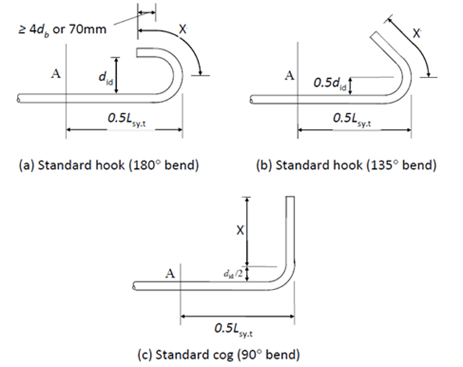
Hooks & Cogs
As per Clause 13.1.2.6, the development length of a deformed bar with a standard hook or cog is shown below.
Hooks and cogs can be useful to reduce the required development length where space or member/connection size does not permit the development length. They can also reduce the reinforcement required in structures, which saves money during construction and is better for the environment.
Worked example: Development length calculation by hand
Consider the minimum development length required for the two terminated 28 mm diameter bottom bars in the concrete beam shown below.
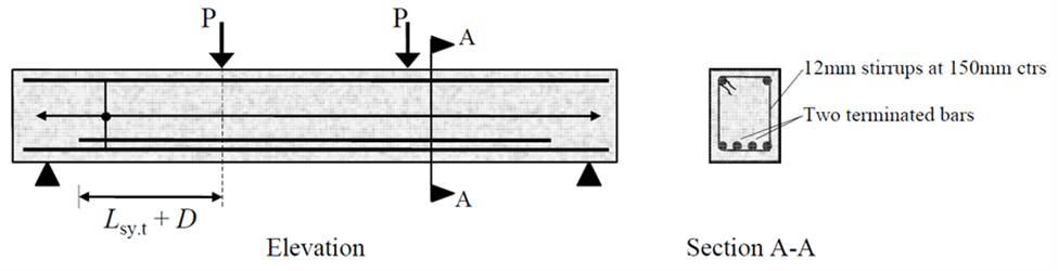
Take $f_{sy}$ = 500 MPa; $f’_c$ = 32 MPa; cover to the 28 mm bars $c$ = 40 mm; and the clear spacing between the bottom bars $a$ = 60 mm.
The cross‐sectional area of one N28 bar is $A_s$ = 620 mm2 and with N12 stirrups at 150 mm centres, $A_{tr}$ = 110 mm2.
For bottom bars: $k_1 = 1.0$;
For 28 mm diameter bars: $k_2 = (132 – 28)/100 = 1.04$;
The concrete confinement dimension, cd = a/2 = 30 mm, and therefore:
$$k_3 = 1.0 – 0.15(30 – 28)/28 = 0.99$$
The basic development length is therefore:
$$L_{sy.tb}= \ge \frac {0.5k_1k_3f_{sy}d_b}{k_2\sqrt{f’c}}=\frac {0.51.00.9950028}{1.04*\sqrt{32}}=1178mm\ge 0.058f{sy}k_1d_b$$
The minimum number of stirrups that can be located within the basic development length is 7.
Therefore: $ΣAtr = 7 x 110 = 770 mm2$.
Taking $ΣAtr.min = 0.25As = 155 mm2$, the parameter $λ = (770 – 155)/620 = 0.99$ can be found.
From Figure 13.1.2.3, $K$ = 0.05 (as it is the two interior bars that are being developed), and therefore, it is assumed that in this location, the transverse pressure perpendicular to the anchored bar ($ρp$) is zero, and hence $k_5$ = 1.0.
$$k_4 = 1.0 − Kλ = 1.0 − 0.05×0.99 = 0.95$$
From Eq. 13.1.2.3 we can determine the refined development length:
$$L_{sy.t}=k_4k_5L_{sy.tb}=0.951.01178mm=1120mm$$
The strength of the beam must be checked at the point where the two bars are terminated (ie. at +d from the constant moment region)
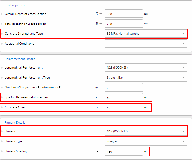
Worked example: Development length using ClearCalcs
We can use the inputs from the hand calculation and enter them into the Concrete Development Length Calculator. Our example is as per the below.
Consider the minimum development length required for the two terminated 28 mm diameter bottom bars in the concrete beam shown below.
Take $f_{sy}$ = 500 MPa; $f’_c$ = 32 MPa; cover to the 28 mm bars $c$ = 40 mm; and the clear spacing between the bottom bars $a$ = 60 mm.
There are N12 stirrups at 150 mm centres.
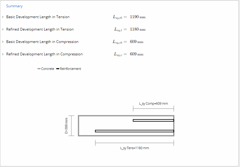
Below are the inputs of the key properties, reinforcement, fitment and stress details into ClearCalcs.
ClearCalcs immediately provides all development lengths for the various design cases to the latest version of AS 3600.
Splicing of reinforcement
Reinforcement splicing refers to the method of connecting two reinforcing bars (rebars) to create a continuous structural element. It’s necessary when the length of a single reinforcement bar is insufficient to cover the entire span or height of a structure. Splicing ensures the continuity of load transfer along the length of the reinforcement.
There are various techniques for splicing reinforcement bars, including:
- Overlap Splicing: This method involves overlapping two rebars and securing them together, usually with tie wire. The length of overlap (lap length) required depends on factors such as bar diameter, concrete strength, and design specifications and is calculated as per the above section of this article.
- Mechanical Splicing: Mechanical splicing involves the use of couplers or mechanical devices to join two rebars together. These couplers are designed to provide load transfer capabilities similar to the strength of a continuous bar. Mechanical splicing can offer advantages in terms of ease of installation, especially in situations where space is limited or where welding is not feasible.
- Welded Splicing: This method involves welding two rebars together to create a continuous length. However, this technique requires careful consideration of welding procedures, material properties, and potential issues related to the welding process, such as heat-affected zones and quality control.
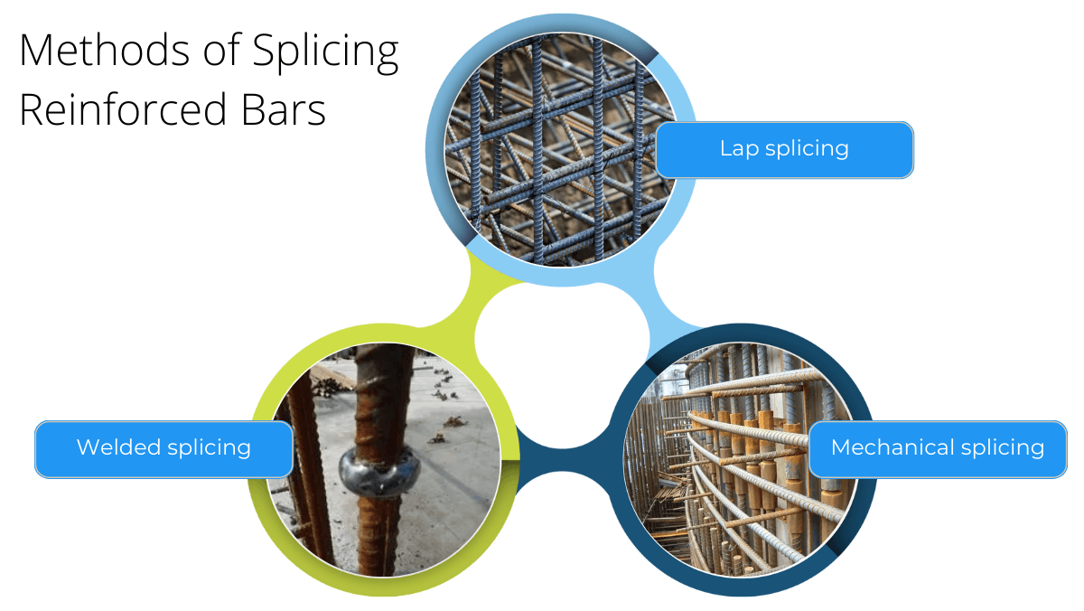
Figure 1: Methods of splicing reinforced bars (Reference)
The choice of splicing method depends on various factors, including structural requirements, site conditions, construction constraints, and design specifications. Engineers must adhere to building codes and standards to ensure the spliced reinforcement maintains the required strength, durability, and structural integrity of the overall construction.
Lapped Splices for Bars in Tension
As per AS 3600:2018 Clause 13.3.3, in wide elements or members (e.g. flanges, band beams, slabs, walls and blade columns), where the bars being lapped are in the plane of the element or member, the tensile lap length (Lsy.t.lap) for either contact or non-contact splices shall be calculated from:
$$L_{sy.t.lap}=k_7L_{sy.t} \ge 0.058f_{sy}k_1d_b$$
Where:
- In the determination of Lsy.t for use in Equation 13.2.2, the lower limit of 0.058fsyk1 in Equation 13.1.2.2 does not apply).
- k7 shall be taken as 1.25 unless the area of steel provided is at least twice the area of steel required and no more than half of the reinforcement at the section is spliced, in which case k7 may be taken as 1.
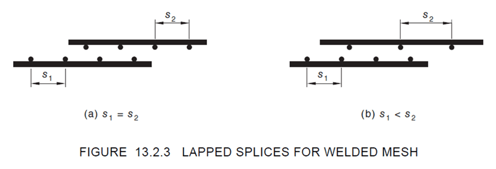
Lapped Splices for Mesh in Tension
A lapped splice for welded mesh in tension shall be made so the two outermost cross-bars spaced at not less than 100 mm or 50 mm apart for plain or deformed bars, respectively, of one sheet of mesh overlap the two outermost cross-bars of the sheet being lapped as shown in Figure 13.2.3. The minimum length of the overlap shall equal 100 mm. A lapped splice for welded deformed and plain meshes, with no cross-bars within the splice length shall be determined in accordance with Clause 13.2.2.
Worked Example: Lapped Splice Requirements
Consider the lapped splice requirements for N12 bars at 200 mm centres in the bottom of a slab. Cover = 20 mm. Concrete strength = 25 MPa.
$$L_{sy.t.lap}=k_7L_{sy.t}=k_7 \frac {0.5k_1k_3f_{sy}d_b}{k_2\sqrt{f’c}} =1.25*\frac {0.51.00.950012}{1.2*\sqrt{25}}=563mm\ge 0.058f{sy}k_1d_b$$
Transmission lengths of pretensioned tendons
Prestressed concrete members use pretensioned tendons rather than passive reinforcement to achieve higher capacities and longer spanning slabs & beams. In absence of test data, the bonded length to develop the stress in seven wire pretensioned strand at ultimate strength shall be taken as not less than:
$$L_p=0.145(\sigma_{pu}-0.67\sigma_{p.ef})d_b$$
where $\sigma _{pu}$ is the stress in the tendon at ultimate strengtha and $\sigma _{p.ef}$ is the effective stress in the tendon after allowing for all losses. Both are in MPa.
Best practices for development length and splicing
Designing lap lengths and splices in reinforced concrete structures involves ensuring the proper transfer of loads between the reinforcement bars while maintaining structural integrity. Best practices consider several factors:
- Code Compliance: Follow the guidelines and specifications provided by relevant building codes (such as ACI 318, Eurocode 2: Design of Concrete Structures, Australian Standards or local standards). These codes provide minimum requirements for lap lengths and splices based on factors like bar diameter, concrete strength, and structural design.
- Structural Analysis: Consider the specific structural design requirements and loading conditions to determine the appropriate lap length or splice location. Engineering calculations should account for the forces acting on the structure and ensure that the chosen method can adequately transfer these forces.
- Material Properties: Consider the properties of both the reinforcement bars and the concrete. Factors such as the yield strength of the rebars, the bond strength between the reinforcement and concrete, and the type of concrete being used influence the design of lap lengths and splices.
- Construction Constraints: Take into account practical aspects of construction, such as accessibility for placing and connecting reinforcement, construction sequencing, and space limitations. Ensure that the selected method is feasible and practical for the construction process.
- Quality Control and Inspection: Implement quality control measures during installation to ensure that the lap lengths and splices are constructed according to the design specifications. Inspections before and after concrete placement are essential to verify the correct placement and alignment of reinforcement.
- Use of Mechanical Splices: Consider using mechanical splices where appropriate. Although mechanical splicing is more expensive, it can offer advantages in terms of ease of installation, quality control, and maintaining structural integrity compared to traditional lap splicing methods.
- Avoiding Congestion: Prevent congestion of reinforcement bars, especially in heavily reinforced areas. Proper spacing and clearances between bars can impact the effectiveness of lap lengths and splices.
Conclusion
In conclusion, the development length of reinforced bars is a crucial aspect of concrete design that ensures the transfer of tensile forces from the steel bar to the surrounding concrete.
AS 3600:2018 provides guidelines for determining the required development length based on factors such as bar diameter, concrete strength, bond strength, and bar position. It is essential for structural engineers in Australia to have a detailed understanding of these guidelines to design safer and more reliable concrete structures.
By utilizing the information and calculations provided in this article, engineers can ensure that the reinforced bars in their designs are properly embedded in concrete and able to develop their full strength.
Seismic Retrofit Series: URM Insights for US and Canada Engineers
August 5th at 1 pm Eastern Time (ET)
Save your spot →Written by:

Kyle Conway
.svg)
Reviewed by:


.png)
