

One of the key concepts in structural design is load tributary width, which refers to the area of a structure that is supported by a particular load.
In this article, we will explore what load tributary width is, why it is important in structural design, and how it is calculated. We will also provide some examples of load width calculations in residential structural design.
Table of Contents
- What are Load Width, Tributary Width, and Tributary Area?
- Applications of Tributary Width
- Examples of Tributary Width Calculations in Residential Structural Design
What are Load Width, Tributary Width, and Tributary Area?
Load width refers to the actual width of a load that is applied on a structure. For example, if you have a beam that is supporting a load, the load width would be the actual width of the object that is being supported by the beam. In other words, load width is the physical dimension of the load itself.
Tributary width, on the other hand, refers to the width of the area on a structure that is supported by a particular element, such as a beam or a column.
For example, if you have a beam that is supporting a floor or a roof, the tributary width would be the width of the area of the floor or roof that is supported by the beam. In other words, tributary width is the area on a structure that is influenced by a particular element or load.
To illustrate this difference further, let's say you have a wall that is supporting a roof. The load width of the roof would be the actual width of the roof, while the tributary width of the wall would be the width of the area of the roof that is directly supported by the wall. This information is important in structural analysis and design, as it helps determine the loads that a particular element or member of the structure will need to support.
Tributary area refers to the total area of the structure that is supported by a particular load. Loads can be either point loads or distributed loads. Point loads are loads that are applied to a specific point on a structure, while distributed loads are loads that are spread out over an area.
Load width and tributary width are not the same things, but they are related. The load width determines the tributary width, which in turn determines the tributary area.
Why is Load Width & Tributary Area Important in Structural Design?
Load width is important in structural design because it helps engineers and architects determine the load-bearing capacity of a structure. By calculating the tributary area, they can determine how much weight a particular part of the structure needs to be able to support.
Engineers can streamline the design process by finding the critical tributary area for a member (e.g., a primary beam), which is the largest area supported by the member and, consequently, the highest loading applied to the member.
Once the primary beam is sized to have sufficient capacity for the critical tributary area loading, then this size beam can be used for all primary beams in the structure, which allows for efficiency in design and economies of scale through procurement.
By using this design procedure, only one set of calculations needs to be performed for each different type of member throughout the whole structure, rather than individually calculating the loading and capacity of every single member.
From the below diagram, the critical tributary area for the beams is CD2-2, so once this loading is calculated and the beam is sized, this beam size can be used for all other beams in the structure.
Similarly, based on the below diagram, the critical tributary area for the columns is B3, so once this loading is calculated and the column is sized, this column size can be used for all other columns in the structure.
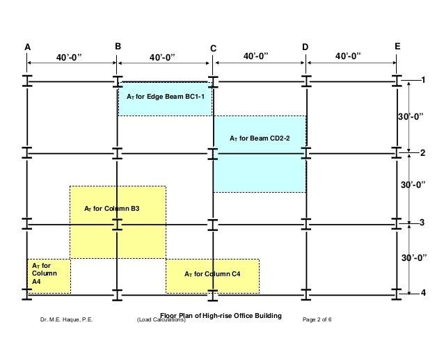
Figure 1: An example of tributary area for columns and beams (Reference)
How is tributary width calculated?
To calculate the tributary width for a distributed load, the area of the load is divided by the distance between the supporting columns or walls.
For example, if a roof has a distributed load of 20 kN per square meter and is supported by two walls that are 20 meters apart, the tributary width of the walls is 10 meters. The load per linear meter would be 200 kN/m, which is the total load of 20 kN/m^2 multiplied by the tributary width of 10 meters.
For concentrated loads, the tributary width is the distance from the center of the load to the nearest supporting column or wall.
For example, if a column is placed 5 meters from a supporting wall and has a load of 10 kN, the tributary width of the column would be 5 meters. The load per linear foot would be 2 kN/m, which is the total load of 10 kN divided by the tributary width of 5 meters.
Applications of Tributary Width
It is more conservative to use tributary width than point loads for bending but not shear.
When calculating the bending moment of a structural member, the load is distributed across the tributary width rather than concentrated at a single point.
This is because the bending moment is a function of the load distribution across the beam, and the moment is greater at points where the load is concentrated.
Therefore, using tributary width for bending calculations is a more conservative approach since it results in a higher calculated bending moment than using point loads, as shown below. This means that the calculated bending stress will also be higher, which can result in a larger beam size or a more conservative design.
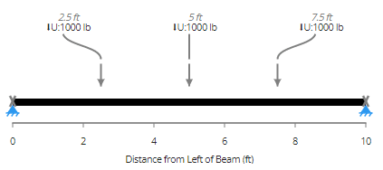
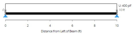
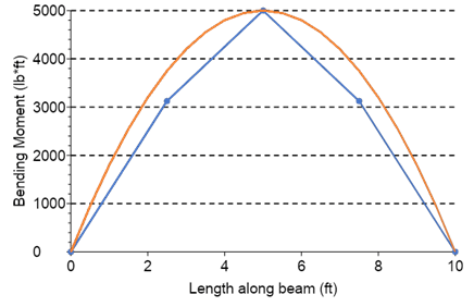
Figure 2: Tributary widths are conservative for bending
On the other hand, when calculating shear in a structural member, the load is distributed uniformly across the member's cross-section, regardless of whether the load is concentrated or distributed.
Therefore, the use of tributary width or point loads does not have a significant impact on the calculated shear. As a result, it is more common to use point loads for shear calculations since it simplifies the analysis without significantly affecting the results.
When designing a cantilever member, the tributary width method may not be conservative since it assumes that the entire load is distributed to the support at the end of the member. However, for a cantilever, the load is not distributed uniformly along the length of the member, and the portion of the cantilever beyond the support does not contribute to the load-carrying capacity of the support.
Therefore, in the case of cantilevered members, using the tributary width method can result in a lower calculated bending moment and may lead to an under-designed structure.
For continuous members, the tributary width method can also lead to non-conservative results because it assumes that each support carries only the load tributary to it. In reality, the load distribution across a continuous member is more complex and may result in load sharing between supports. This can result in a situation where a particular support is carrying a load greater than what is calculated using the tributary width method, leading to potential structural issues.
In residential projects, the use of incorrect load calculations can lead to a structure that is not strong enough to support its intended loads, which can result in safety issues and building failures.
Therefore, it is crucial for structural engineers to carefully consider the load distribution and use appropriate analysis methods to ensure that the structure is adequately designed for its intended use.
In the case of cantilevered members and continuous members, using more advanced analysis methods, such as finite element analysis or moment distribution analysis, may be necessary to accurately determine the load distribution and ensure the structure's safety and stability.
Fortunately, shear is not critical in residential timber and steel construction, and cantilevered & continuous members are less common, so tributary width is usually conservative and applicable for residential design.
Examples of Tributary Width Calculations in Residential Structural Design
Roof Tributary Width & Tributary Area on Columns
Let's take the example of a rectangular room with dimensions of 7 meters by 4 meters, and a flat roof supported by three primary beams and four columns placed at the corners of the room. The ceiling and floor have a weight of 3 kN/m^2 as per the below diagram.
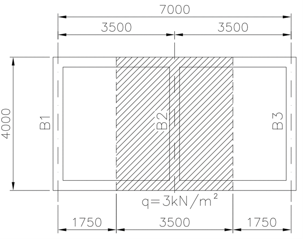
Figure 3: An example of a simple residential structure
The tributary width of each column supporting the roof will be half the distance to the adjacent columns, as the load on the roof is evenly distributed.
Therefore, the roof tributary area on the columns will be 3.5 meters (half the distance between columns along the width of the room) by 2 meters (half the distance between columns along the length of the room), which is 7 square meters. Therefore the load on the corner columns will be 7 square meters by the roof load of 3 kN/m^2 which is 21 kN.
Roof Tributary Width & Tributary Area on Beams
Using a similar example above, the tributary width is half of the spacing between the vertical beams. Given the structural arrangement in the above diagram, the loads on the beams B1, B2, and B3 can be calculated as per the below.
For Beam B2, the tributary width will be 3.5 meters, giving a tributary area of 14 square meters when the tributary width is applied across the 4-meter length of the beam. The load on Beam B2 is found by multiplying the applied roof load of 3kPa by the tributary width of 3.5m, which gives 10.5 kN/m.
Beam B1’s tributary width is 1.75 meters which is half of the spacing between the vertical beams and is the same as Beam B3 (edge beam). The load on Beam B1 is found by multiplying the applied roof load of 3kPa by the tributary width of 1.75m, which gives 5.25 kN/m.
When calculating the loads using ClearCalcs templates, the tributary width should be inputted into ClearCalcs as shown below.

Figure 4: The input for tributary width in ClearCalcs (Reference)
Roof Tributary Width & Tributary Area on Skewed Beams
The tributary width can also be calculated for skewed beams. Let’s take the below example of the top-right skewed primary beam where a uniform load of 10 kN per square meter is applied to the entire floor.
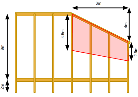
Figure 5: An example of a structure with skewed beams
First, the length of the beam is calculated below:
L=√(6^2+4^2=7.21m)
Left end load=10 kN/m^2*4.5m=45 kN/m
Right end load=10 kN/m^2*2.5m=25 kN/m
This can be inputted into ClearCalcs as per Figure 5 below.
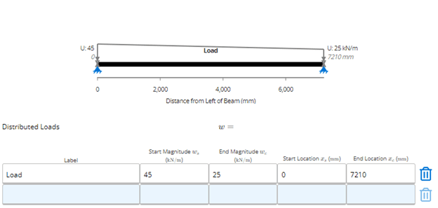
Figure 6: How to enter tributary widths for skewed beams in ClearCalcs
ClearCalcs can even perform these calculations for us by providing an easy way to enter area loads by providing four dimensions and the area load as per the below example that shows the inputs.
- Start Location (x_s) - area loading may start at any point along the beam (e.g., only applied on one span)
- End Location (x_e)
- Start Load Width (TW_s) - may be different than TW_e, as shown in Figure 6
- End Load Width (TW_e)
- Load Magnitude / Area Load (w)
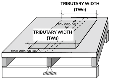
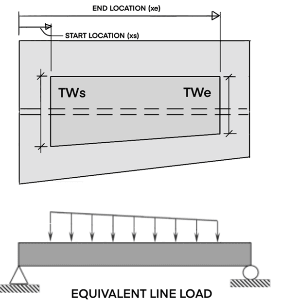

Figure 7: Tributary widths can be transferred into distributed loads using ClearCalcs (Reference)
Roof Tributary Width & Tributary Area on Split Beams
The tributary width can also be calculated for split beams.
Let’s take the below example of the bottom horizontal split primary beam where a uniform load of 10 kN per square meter is applied to the entire floor.
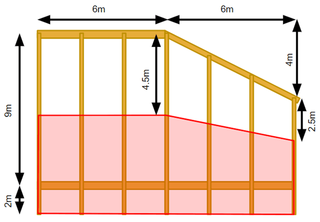
Figure 8: An example of a stucture with split beams
Left end and middle load=10 kN/m^2*(4.5m+2.5m)=65 kN/m Right end load=10 kN/m^2*(2.5m+2m)=45 kN/m
Be sure to watch our residential structural expert, Laurent Gérin’s Load & Tributary Width Webinar which shows more examples of how to easily calculate a broad range of tributary and load widths you may encounter on your projects and how then to use the incredibly flexible load entry tools in ClearCalcs to ensure you get a great design quickly.
Conclusion
Load tributary width is an essential concept in structural design that helps engineers and architects determine the load-bearing capacity of a structure.
By calculating the tributary area, they can ensure the safety and stability of a structure, especially in residential structural design. Aspiring engineers and designers must familiarize themselves with these concepts to create stable, safe and efficient structures. The design process can be streamlined when the largest tributary area is used to design members that can be used across the whole structure.
It is important to note that load width calculations can vary depending on the type of load, and it is critical to follow the appropriate standards and codes when conducting load width calculations.
Seismic Retrofit Series: URM Insights for US and Canada Engineers
August 5th at 1 pm Eastern Time (ET)
Save your spot →Written by:

Kyle Conway
.svg)
Reviewed by:


.png)
