
Roof steel trusses are common structural systems used to design and construct various buildings, including residential, commercial, and industrial structures, to span large distances (Heyman, 2010). These trusses consist of a series of interconnected steel members, typically arranged in a triangular pattern, that provide support and stability for the roof.
The design and analysis of roof steel trusses are critical to ensuring the structural integrity and safety of the building.
This article discusses the approach to analyzing and designing a steel roof truss by providing a typical case study and comparing various tools commonly used to analyze truss design.
Introduction
In the United States, the design and analysis of roof steel trusses are typically based on the American Institute of Steel Construction (AISC) 360-22: Specification for Structural Steel Buildings (AISC, 2022).
This specification provides guidelines for the design, fabrication, and erection of structural steel for buildings and other structures such as bridges and towers. The AISC specification includes specific provisions for the design and analysis of roof steel trusses to ensure that they can withstand the various loads and stresses they may be applied to during their lifetime.
The first step in designing a steel roof truss is to determine the loads to which the truss will be subjected. These loads include dead loads, which are the weight of the roof itself and any permanent equipment or structures attached to it, as well as live loads, which are the weight of temporary items that may be present on the roof.
In addition, the truss may be subjected to wind loads, which are caused by the wind blowing on the roof, and snow loads, which are caused by the weight of snow that may accumulate on the roof.
Once the loads have been determined, the design engineer can begin to determine the appropriate size and configuration of the steel members that will make up the truss. This typically involves using computer software that can perform complex calculations to determine the optimal design. Some of the factors considered are the strength of the steel members, the distance between the members, and the angle of the members relative to one another.
Design Factors in Steel Trusses
When designing a steel roof truss using American standards, structural designers must consider several essential factors to ensure that the roof is safe, durable, and capable of withstanding the loads and stresses that it will be subjected to over time.
Applied Loads
Applied loads are divided into gravity and lateral loads.
- Gravity loads typically subjected to a truss include dead loads (the weight of the roof itself), live loads (the weight of any objects or people on the roof), and snow loads.
- Lateral forces typically imposed on a truss structure include wind and seismic loads, which must also be considered when designing a steel roof truss using the American standard.
In this regard, American standards requirements must be carefully evaluated to ensure that the roof is designed to support the necessary loads without collapsing or experiencing excessive deflection.
Material Selection
Another key consideration when designing a steel roof truss is the material selection, as it will determine the overall strength and durability of the roof.
The American standard AISC 360-22: Specification for Structural Steel Buildings provides guidelines for the steel's minimum yield strength and other properties, as well as the allowable stress levels.
Examples of steel materials include:
- A36: This is the most commonly used structural steel grade, with a minimum yield strength of 250 MPa (36 300 psi). It is suitable for most truss applications, particularly where the load is not too high.
- A572: This grade is used for heavy loads requiring higher strength and is available in several grades, including 42, 50, 55, 60, and 65.
- A992: This is the newest grade of structural steel and has a minimum yield strength of 345 MPa (50 000 psi). It has a higher strength-to-weight ratio than A36 and A572, making it suitable for long-span trusses with heavy loads.
- A500: This grade is carbon steel generally used in steel tubing, where truss elements are typically made. Like A572, it has multiple grades and classes depending on the section constructed. This grade is the most used in the HSS sections that are widely adopted in roof trusses.
Section Selection
Various structural sections can be used when erecting a steel roof truss, depending on the design and loading requirements. Some common structural sections used in steel roof truss construction include:
- Hollow structural sections (HSS): These are steel tubes that can be square, rectangular, or circular in shape and are commonly used as truss members.
- Angles: These are L-shaped sections that are commonly used to connect the various members of a truss, such as the chords and web members.
- Channels: These are U-shaped sections that can be used as chords or web members in a truss.
- Pipes: Steel pipes can also be used as truss members and are often used as tension members in trusses.
- I-beams: Also known as W-beams or wide flange beams, these sections have an I-shaped cross-section and can be used as truss chords.
- Tee sections: These sections have a T-shaped cross-section and can be used as chords or web members in a truss.
The selection of the appropriate structural sections for a steel roof truss depends on factors such as the span, the loading requirements, the design criteria, and the available materials.
Truss Geometry
Truss geometry is another critical factor when designing a steel roof truss.
In general, truss geometry refers to the physical dimensions and layout of a truss structure. The height and width of a truss are typically determined by the specifications of the structure it is intended to support.
For example, the height of a roof truss might be based on the desired slope or pitch of the roof, while the width might be determined using the overall width of the building or the spacing between support columns. The number of unit panels that make up the truss width can vary depending on the design and the load-bearing requirements of the structure. Typically, a truss is composed of a series of interconnected triangles that distribute weight and stress evenly throughout the structure.
The number of triangles, and therefore the number of unit panels, depends on the size and shape of the truss. Generally, these parameters are selected based on the architectural contexts, the owner's preferences, and some structural and construction limitations, which vary from one case to another.
Currently, various types of trusses can be used in a steel structure.
In general, the truss geometry selected must be followed closely to ensure that the truss is designed to provide adequate strength and stability while minimizing the amount of material required and meeting the architects' and owners' objectives. Examples of common truss geometries and descriptions of various types of trusses can be found in this article.
Fire Resistance
Fire resistance is also important when designing a steel roof truss, where the roof is expected to meet certain fire resistance ratings as specified in American standards, such as the AISC 360 and the National Fire Protection Association (NFPA)'s standards NFPA 5000 and NFPA 220.
Modeling Assumptions
Truss elements are typically considered pin-connected because they are designed to primarily resist axial loads (tension or compression) and not bending moments.
A pin connection between the truss members is a simple hinge or pin joint, which allows the members to rotate freely relative to one another.
This type of joint is also known as a pinned or hinged joint, and it is a common feature in truss structures. The reason for using pin-connected joints in truss structures is that no shear or bending forces are transferred from one member to another, and only axial forces are transferred in between members.
In contrast, frame elements such as beams are designed to resist both axial, shear, and moment loads, and they are usually connected using fixed or semi-fixed (moment-resistant) connections. These connections can resist axial and shear loads and bending moments but are typically more complicated to analyze than pin-connected joints.
Nevertheless, in some design cases, truss elements are considered frame elements, given that they are welded elements that pose certain resistance against rotation.
Another design assumption is typically made in which the chords are frame elements while the diagonal and vertical elements are truss elements (pinned at the ends).
This assumption emerges from the fact that the chords are typically made of a single continuous steel element that poses rigidity, whereas the diagonal and vertical elements are welded to the chords. Hence, the connections between diagonal and vertical elements and the chords are approximated as pinned to simplify calculations while efficiently resisting axial loads, even though they are physically welded. This approach acknowledges that the actual behavior of the structure might deviate slightly from the assumptions made.
In this section, a comparison between various joint connection assumptions will be provided for a typical truss case.
Let us consider a typical Warren truss, as shown in Figure 1. Assume that the loads applied include the self-weight of the truss as well as a 685 lb/ft uniformly distributed force on the top chord.
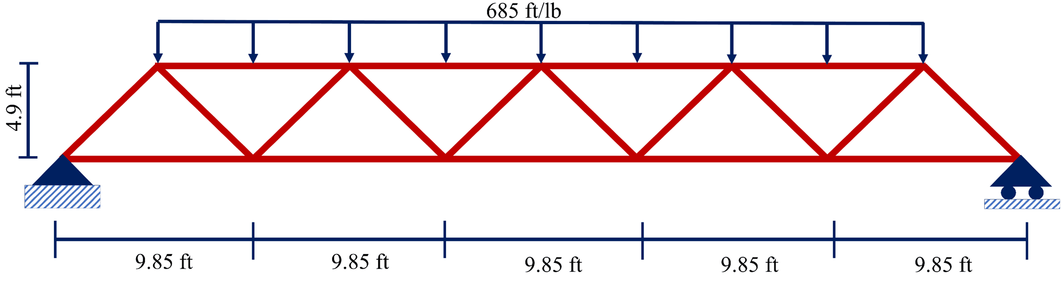
Figure 1: An example of a Warren truss subject to a 685 lb/ft distributed load
Figure 2 shows the results of the analysis for three various cases.
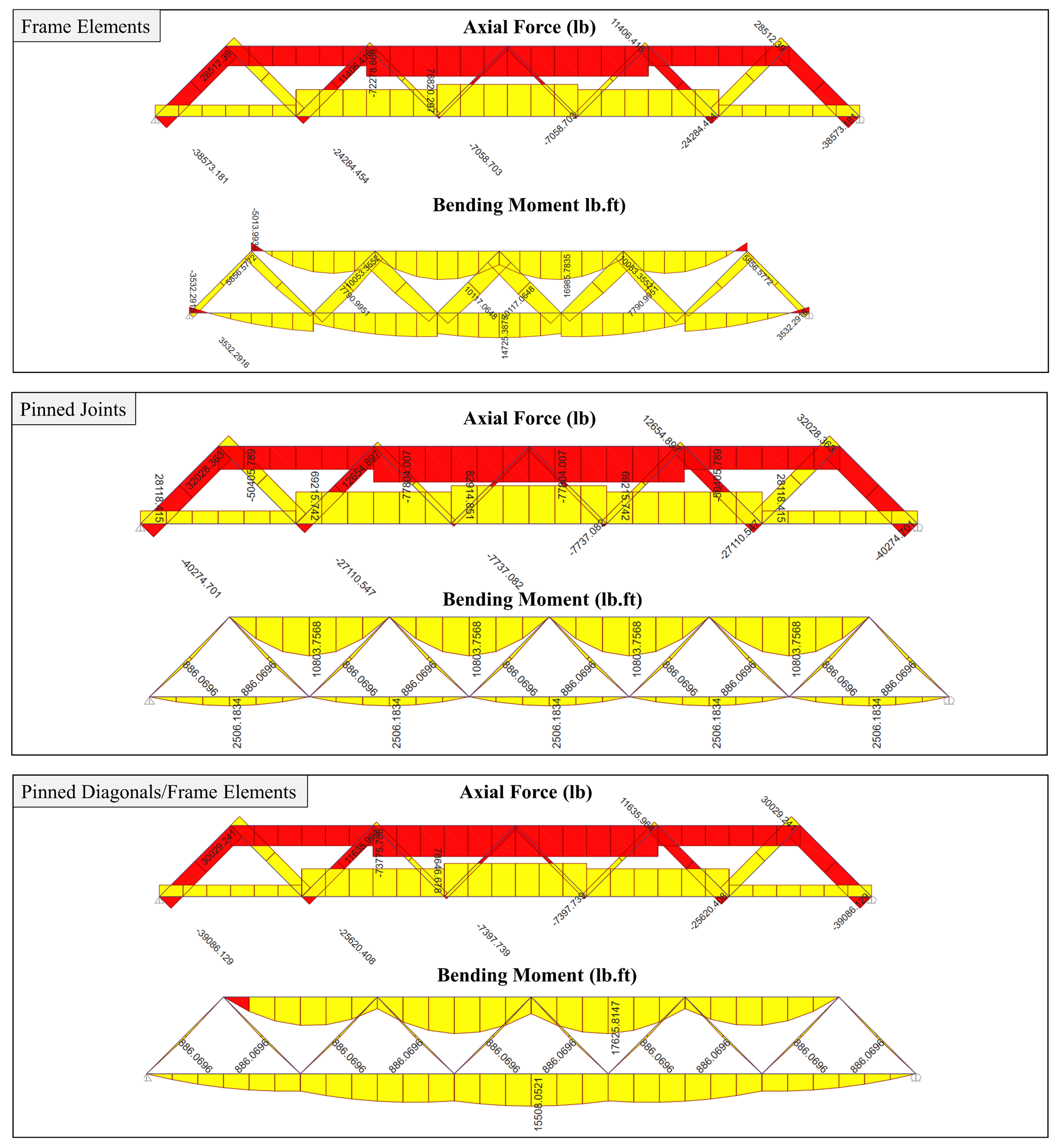
Figure 2: Truss analysis based on various joint analysis
Additionally, Table 1 summarizes the peak internal forces and bending moments.
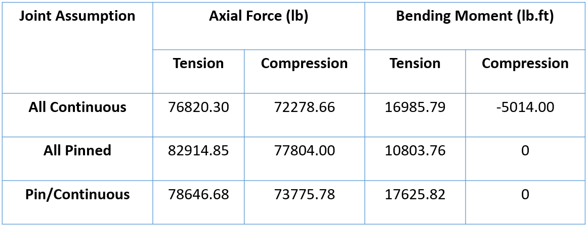
Table 1: Comparison between the maximum forces/moments under various joints' assumptions
It can be seen that all forces are close in value, with the highest internal axial force being observed in all pinned cases and the highest tension bending moment in pinned/continuous, whereas the highest compression bending moment is achieved in the continuous case.
Design Example
The design example herein is a Pratt roof truss design assumed to be located in Texas, USA. The building has a length of 131 ft and a width of 29.4 ft.
Defining the Truss Geometry
In this example, the roof truss is taken with a height of 4.9 ft and six unit panels, each with 4.9 ft in width.
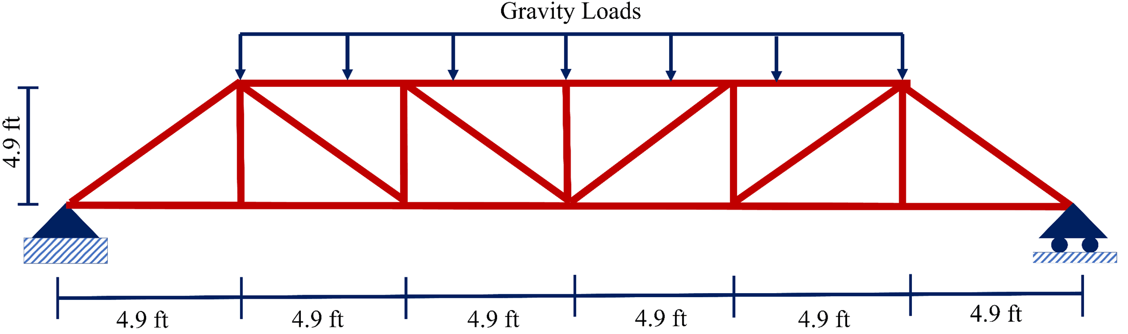
Figure 3: Description of the Pratt roof truss design example adopted in this article
Selecting Truss Material and Section
The truss is assumed to be built of A500 steel grade. The selection of the material is typically based on the availability in the market and the intended level of stress to be applied. For instance, the A500 grade offers a 6,620,682 lb/ft2 yielding strength, which is a good value for a roof truss application.
Once the material is selected, the next step is to select the steel section. Various sections can be found in the AISC specifications. However, a truss is commonly made of hollow square or rectangular sections. For this reason, the square hollow structural section HSS3-1/2X2-1/2X.250 section is selected as the initial guess during the design for all elements, and its capacity will be checked once the load analysis is completed. Thereafter, the section size can be optimized based on the demand/capacity ratio for the tension and compression section in the top and bottom chords, as well as the diagonal and vertical elements.
Accordingly, the process of selecting the truss material and section is the truss design stage in which the properties of the truss are all set.
Calculating Total Distributed Loads
The gravity loads (dead and live loads) are typically applied to the top and bottom chords of a truss in different ways, depending on the specific design and intended usage of the truss.
For example, in a pitched roof truss, the gravity loads are applied to the top chord of the truss. The bottom chord may also be designed to resist the weight of any occupants or equipment that may be located in the attic space.
A similar concept is also used in floor trusses, where the gravity loads are typically applied to the top chord of the truss, while the bottom chord carries the weight of occupants, furniture, and other moveable objects.
In this example, the truss is designed to support gravity loads, including both dead (342 lb/ft) and live (154 lb/ft) loads. These loads are obtained by distributing the roof loads to the truss and then are applied as line loads during the analysis, and the combination given in Eq. 1 is used as recommended by the American standard.
Load combination = 1.2 Dead load + 1.6 Live load (Eq. 1)
Figure 4 shows the results for the truss analyses using the ETABS and the ClearCalcs Truss Analysis Wizard. It is evident that the results from ClearCalcs match with the results from ETABS, as seen in Figure 5.
Additionally, it can be seen that the maximum axial load is about 14,400 kN and 12,700 kN for compression and tension. These values must be taken to check whether the selected section provides sufficient capacity to resist the applied loads.
Accordingly, based on the selected material and section properties, the HSS3-1/2X2-1/2X.250 section provides sufficient capacity, as highlighted in the AISC specifications.
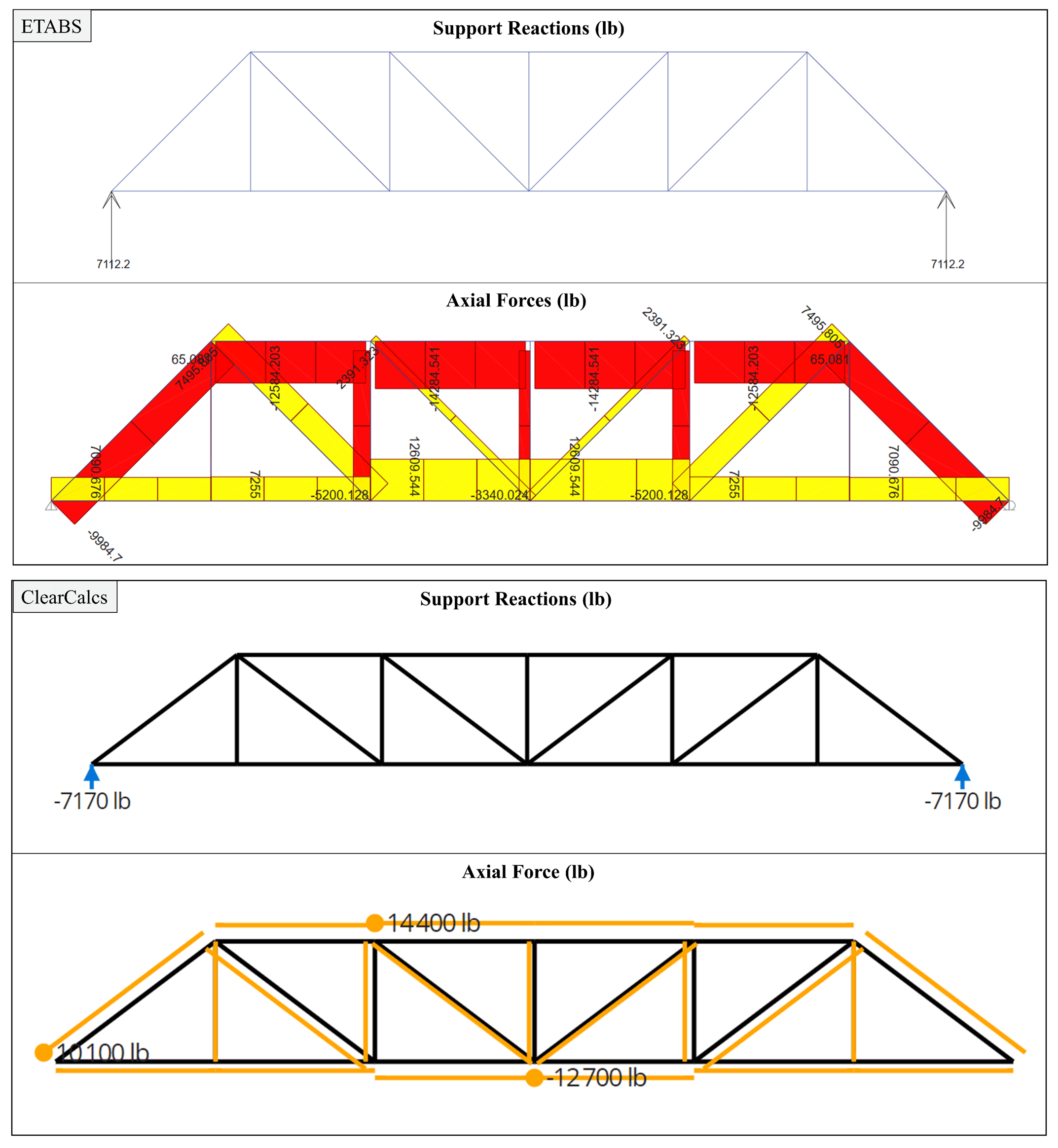
Figure 4: Results of the Pratt roof truss analysis using ETABS and ClearCalcs
Conclusion
Based on the aforementioned statements, the following conclusions can be drawn:
- The American Institute of Steel Construction (AISC) specification provides guidelines for the design, fabrication, and erection of structural steel for buildings and other structures.
- To ensure structural integrity and safety, the loads to which the truss will be subjected must be carefully determined.
- The material selection is critical to ensuring the overall strength and durability of the roof, and the American standard provides guidelines for the steel's minimum yield strength and other properties, as well as allowable stress levels.
- Truss geometry is an important factor to consider when designing a steel truss roof, where various types of trusses can be used in a steel structure.
- Truss elements are typically pin-connected, allowing for efficient resistance to axial loads without inducing significant bending stresses or moments, but in some cases, they may be considered continuous, posing resistance against rotation and inducing lower axial force compared to pin connections.
- Trusses' force analyses can be time-consuming when performed manually; however, using a professional tool can save huge efforts while yielding accurate and reliable results.
Overall, the practical analysis and design of steel roof trusses require careful consideration to ensure a safe and durable structure capable of withstanding the loads and stresses it may encounter over time. ClearCalcs Truss Analysis Wizard can easily determine the cumulative load applied, support reactions, bending moment, shear and axial forces, extension and displacement for each chord of the truss by inputting the truss geometry and load conditions.
Ready to start calculating in ClearCalcs?
You can use the account for 14 days for free, with no commitment required. Need ClearCalcs for a one-off project? Subscribe to our month-to-month plan and cancel anytime, no questions asked.
References
- AISC. (2022). AISC 360-22: Specification for Structural Steel Buildings.
- Heyman, J. (2010). Design of a simple steel truss.
Seismic Retrofit Series: URM Insights for US and Canada Engineers
August 5th at 1 pm Eastern Time (ET)
Save your spot →Written by:

Dr. Ahed Habib
.svg)
Reviewed by:


.png)
