

Introduction
A live load pattern refers to the distribution or arrangement of live loads, which are temporary and variable loads on a structure, such as people, furniture, or vehicles. The live load pattern helps structural engineers analyze and design a structure by considering how these dynamic loads are distributed across the surface.
There are different live load patterns based on the expected usage of the structure. Common live load patterns include:
- Uniformly Distributed Load (UDL): The live load is evenly spread over the entire area, such as in the case of office buildings where furniture and occupants are distributed uniformly.
- Concentrated Load: This pattern involves a significant load applied at a specific point, like the weight of a heavy piece of equipment or a crowd gathered in one area.
- Line Load: The live load is concentrated along a line, often seen in scenarios like storage racks in warehouses or people queuing in a specific line.
- Two-Way Distribution: It represents a combination of uniformly distributed load and concentrated load, common in structures like bridges where the load is distributed from multiple lanes.
In structural design, engineers consider combinations of live load and dead load, along with other applicable loads (such as wind or seismic loads). Load combinations help account for the simultaneous occurrence of different loads, ensuring that the structure is robust under various conditions.
Live load patterning is essential to ensure that the structure is designed to withstand dynamic forces in a realistic and representative manner. It aids in preventing localized overloading and guides the engineer in designing elements to accommodate variations in loading conditions.
The Importance of Load Patterning
In residential or light commercial structural design, understanding and considering live load patterns are crucial for several reasons:
Occupant Safety
Residential and light commercial structures are often designed to accommodate various activities, such as furniture placement, social gatherings, or storage. Different live load patterns help engineers ensure that the structure can safely support these activities without the risk of failure.
Code Compliance
Building codes provide guidelines for the minimum live load requirements based on the type of occupancy. By correctly accounting for live load patterns, engineers ensure that the structure complies with relevant building codes, meeting safety standards and regulations.
Structural Integrity
Live load patterns help in distributing loads uniformly across the structure. Proper distribution prevents localized stresses, minimizing the risk of structural deformations, cracks, or failures over time.
Adaptability to Changing Loads
Residential structures may experience varying live loads based on changing furniture arrangements or occupancy. Understanding live load patterns allows engineers to design structures that can adapt to these fluctuations without compromising safety.
Efficient Material Usage
By accurately assessing live load patterns, structural engineers can optimize the use of materials. This efficiency is especially crucial in residential and light commercial projects where cost-effectiveness is a significant consideration.
Practical Examples of Live Load Patterning in Residential or Commercial Structural Design
Structural engineers need to consider live load patterning in their design across various scenarios to ensure the safety and functionality of structures.
Here are some key scenarios where live load patterning is crucial in building design:
Residential Structures
Scenario: Designing a residential building with different spaces like bedrooms, living rooms, and kitchens.
Importance: Live load patterning ensures that the structure can safely support varying furniture arrangements and occupant activities in different areas.
Commercial Buildings
Scenario: Designing an office building with open workspaces, meeting rooms, and circulation areas.
Importance: Understanding live load patterns helps in distributing the load uniformly, considering the density of occupants and the type of activities in different zones.
Retail Spaces
Scenario: Designing a retail store with display areas, checkout counters, and storage spaces.
Importance: Live load patterning is essential to accommodate the dynamic nature of retail spaces, where the distribution of loads varies based on the location of shelves, displays, and foot traffic.
Educational Facilities
Scenario: Designing a school building with classrooms, auditoriums, and common areas.
Importance: Live load patterns help account for concentrated loads in spaces like auditoriums and ensure the structural integrity of classrooms with movable furniture.
Bridges and Walkways
Scenario: Designing a pedestrian bridge or walkway in a public space.
Importance: Live load patterning is critical to consider the concentrated loads from crowds and the dynamic movement of people in different sections of the bridge.
Industrial Structures
Scenario: Designing a warehouse with storage racks and machinery.
Importance: Live load patterns are necessary to account for concentrated loads from heavy equipment, forklifts, and storage configurations that vary in different areas of the warehouse.
Code Provisions for Live Load Patterning in the United States and Australia
In both the United States and Australia, building codes outline requirements for live loads in structural analysis. Here are examples of relevant building codes:
United States
International Building Code (IBC)
The IBC is widely adopted across the United States. It provides guidelines for live loads based on occupancy type. For example, residential live loads are specified in pounds per square foot (psf), and different patterns are considered based on the function of the space.
ASCE 7 (Minimum Design Loads for Buildings and Other Structures)
This standard, published by the American Society of Civil Engineers (ASCE), is referenced in the IBC. It details live load provisions, including different load patterns, for various structures.
ACI 318-19 - Building Code Requirements for Structural Concrete
- ACI 318-19, Section 4.4 - Live Load Patterns: This section of the ACI code provides guidelines on live load patterns for different types of concrete structures. For instance, it outlines patterns for residential buildings, specifying how loads from various rooms and spaces are to be considered in structural analysis.
- ACI 318-19, Section 4.4.1 - Balcony Live Loads: Specific provisions are made for balcony live loads, addressing concentrated loads and distributed loads based on the intended use of the balcony space.
Australia
National Construction Code (NCC)
The NCC is the primary code in Australia for the construction of buildings. It includes live load requirements for different occupancy classes and specifies patterns for areas such as residential, commercial, and industrial spaces.
Australian Standard AS 1170.1 - Structural Design Actions
This standard provides specific guidelines for live loads and their patterns, considering factors such as occupancy, intended use, and spatial distribution.
AS 3600-2018 - Concrete Structures
- AS 3600-2018, Clause 3.4 - Live Loads: This clause provides details on live loads and their patterns for different occupancy classes. It addresses variations in live loads for residential, commercial, and industrial structures, ensuring that engineers consider the specific requirements for each.
- AS 3600-2018, Clause 4.4 - Uniformly Distributed Loads: This clause specifies the distribution of live loads, particularly uniformly distributed loads, for different elements of concrete structures. It provides insights into the patterns to be used in the analysis and design of elements like slabs and beams.
Tools for Live Load Patterning in Structural Design
Structural engineers use various tools and software to apply live load patterning in their structural calculations. These tools aid in efficiently analyzing and designing structures to ensure they can withstand dynamic loads. Here are some commonly used tools:
Structural Analysis Software
Examples: SAP2000, ETABS, RISA, STAAD Pro
Functionality: Structural analysis software allows engineers to model the structure and apply different live load patterns. These tools provide features to distribute live loads across elements, assess deflections, and analyze the overall structural response.
Building Information Modeling (BIM) Software
Examples: Autodesk Revit, Tekla Structures
Functionality: BIM software enables engineers to create detailed 3D models of structures, integrating architectural and structural elements. Live load patterning can be applied within these models to visualize and analyze how loads are distributed throughout the structure.
Spreadsheets and Calculation Tools
Examples: Microsoft Excel, Mathcad
Functionality: Engineers often use spreadsheets or calculation tools to perform hand calculations and apply live load patterns. These tools allow for flexibility in customizing calculations based on specific project requirements.
Specialized Structural Design Software
Examples: ClearCalcs, SkyCiv
Functionality: Specialized tools designed for structural engineering, such as ClearCalcs, offer features specifically tailored to the needs of engineers. These tools may include pre-built templates, libraries of standard calculations, and intuitive interfaces for easily applying live load patterning.
Finite Element Analysis (FEA) Software
Examples: Abaqus, ANSYS
Functionality: FEA software is used for detailed analysis of complex structures. Engineers can apply live load patterns and observe how these dynamic forces affect the behavior of individual elements within the structure.
Code-Specific Software Modules
Examples: SAFE for slab design, RAM Elements
Functionality: Some software tools offer modules specifically designed to address live load patterns in accordance with building codes. These modules often streamline the application of code-specific requirements for different load scenarios.
Load Rating Software
Examples: LARSA, Conspan
Functionality: Load rating software is used for assessing the capacity of existing structures. Engineers can input live load patterns to evaluate the load-carrying capacity of elements, especially in the context of renovations or upgrades.
In a practical setting, engineers may use a combination of these tools based on project requirements, preferences, and the complexity of the structural analysis. The goal is to leverage technology that facilitates accurate live load patterning and ensures compliance with safety standards and building codes.
Worked Example: Hand Calculations
- Length of the beam (L) = 8 meters
- Spans (S1, S2, S3) = 2.5 meters, 3 meters, and 2.5 meters, respectively
- Dead load (including concrete) = 4.6 kPa
- Live load = 4.8 kPa
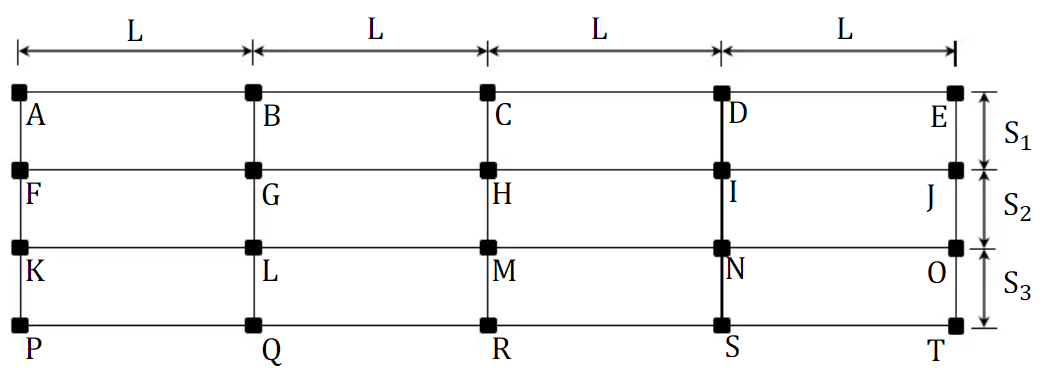
We want to determine the maximum factored reaction (RLmax) at the first interior support (L), the minimum factored reaction (ROmin) at the exterior support (O), and the maximum factored moment (M_Lmax) at the first interior support (L).
Step 1: Calculate the Tributary Width (S)
First, calculate the tributary width for the beam, denoted as 'S'. It is half the sum of S2 and S3.
$$S = (S2 + S3) = = (3.0 + 2.5) = 2.75 \text{ meters}$$
Step 2: Determine Factored Uniform Dead Load (Wdu) and Factored Uniform Live Load (Wlu)
Next, calculate the factored uniform dead load (Wdu) and factored uniform live load (Wlu) using the provided load factors:
$$\text{Factored dead load} (W_{du}) = 1.2 × \text{Dead load} × \text{Tributary Width} = 1.2 × 4.6 kPa × 2.75 m = 15.18 kN/m$$
$$\text{Factored live load }(W_{lu}) = 1.6 × \text{Live load} × \text{Tributary Width} = 1.6 × 4.8 kPa × 2.75 m = 21.12 kN/m$$
Step 3: Calculate Maximum Factored Reaction at L_(RLmax)
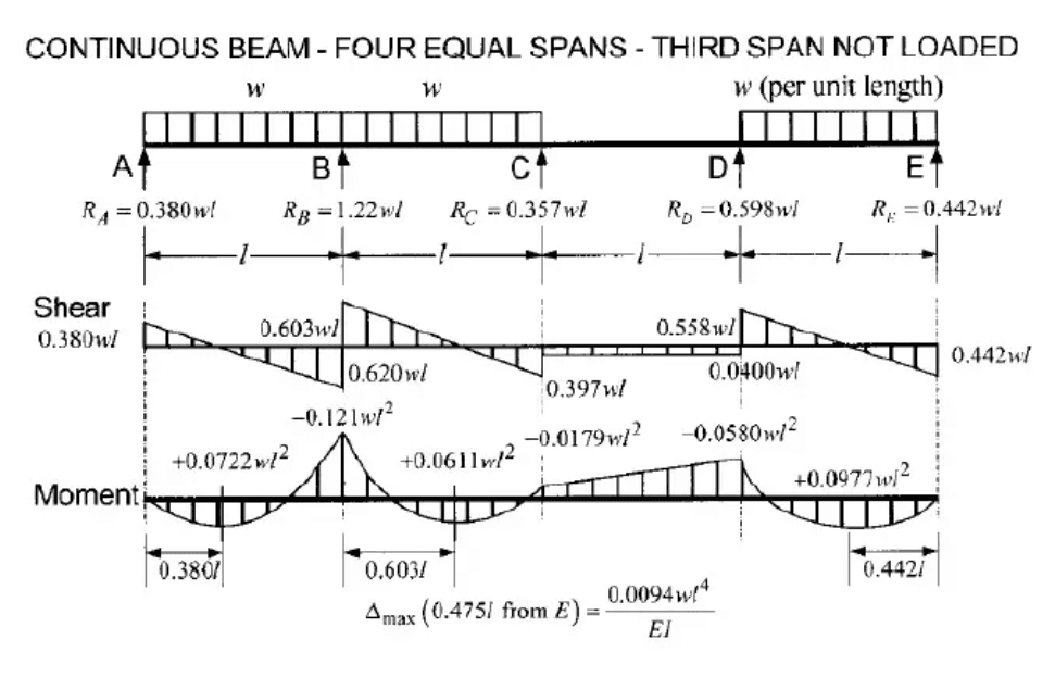
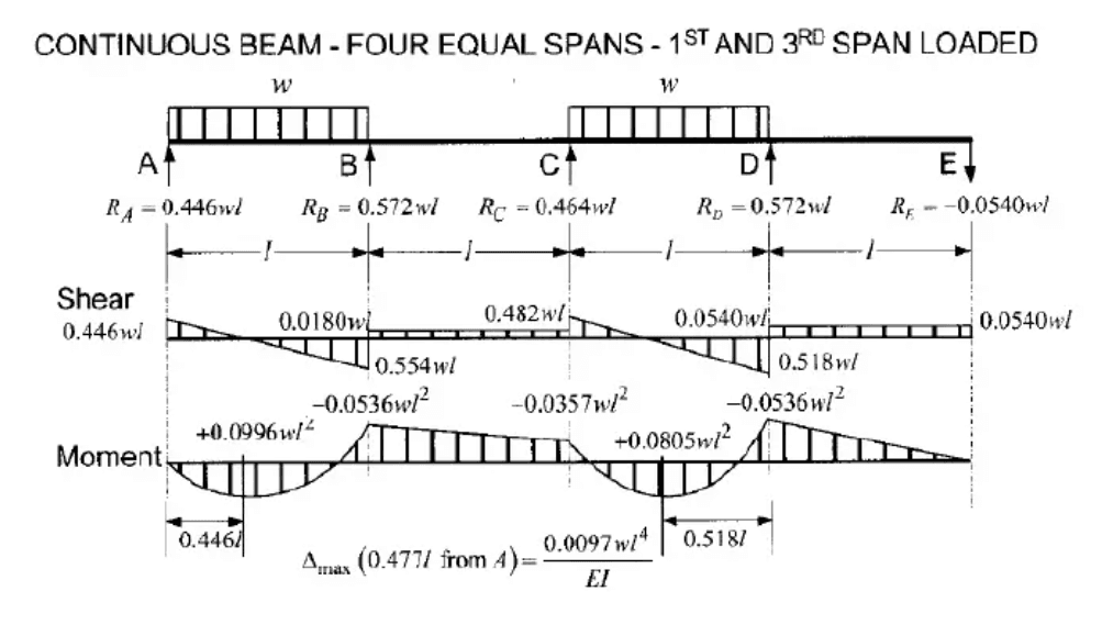
To find the maximum factored reaction at the first interior support (L), apply pattern loading for the live load:
$$R_{Lmax} = 1.143 × W_{du} × L + 1.223 × W_{lu} × L$$
$$R_{Lmax} = 1.143 × 15.18 kN/m × 8 m + 1.223 × 21.12 kN/m × 8 m$$
$$R_{Lmax} ≈ 345.44 kN$$
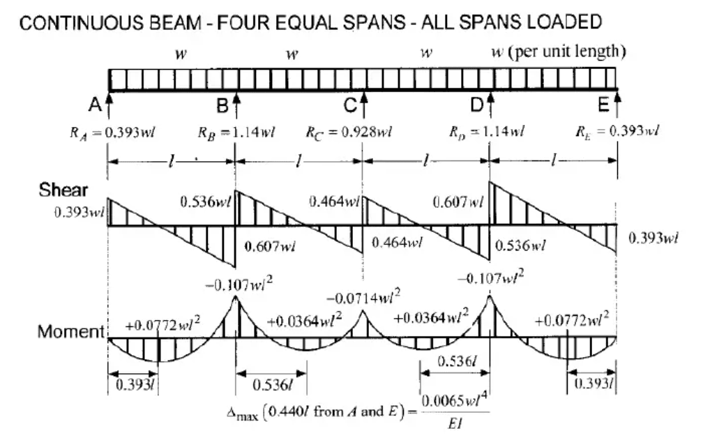
Step 4: Calculate the Minimum Factored Reaction at O(ROmin)
To determine the minimum factored reaction at the exterior support (O), apply pattern loading for the live load:
$$R_{Omin} = 0.393 × W_{du} × L - 0.054 × W_{lu} × L$$
$$R_{Omin} = 0.393 × 15.18 kN/m × 8 m - 0.054 × 21.12 kN/m × 8 m$$
$$R_{Omin} ≈ 38.602 kN$$
Step 5: Calculate the Maximum Factored Moment at L(MLmax)
For the maximum factored moment at the first interior support (L), apply the pattern loading for the live load:
$$M_{Lmax} = 0.1071 × W_{du} × L^2 + 0.1205 × W_{lu} × L^2$$
$$M_{Lmax} = -0.1071 × 15.18 kN/m × (8m)^2 - 0.1205 × 21.12 kN/m × (8m)^2$$
$$M_{Lmax} ≈ -266.93 kN·m$$
In this worked example, we have successfully applied pattern loading principles to calculate the maximum factored reaction at L, the minimum factored reaction at O, and the maximum factored moment at L for the given beam. These calculations are essential for ensuring structural safety and integrity in beam analysis
How ClearCalcs Provides a Time-Saving Alternative for Live Load Patterning
Conventionally, structural engineers need to perform manual calculations of each structural element iteratively based on the live load patterns. This manual approach can be time-consuming and may require meticulous attention to detail, making it more susceptible to errors compared to automated methods provided by specialized software tools like ClearCalcs.
Engineers designing wood, concrete, or steel beams to US building codes can now enable automated live load patterning in ClearCalcs. By enabling this feature, ClearCalcs will automatically create load combinations for distributed (psf) and line (plf) live loads for all continuous beams.
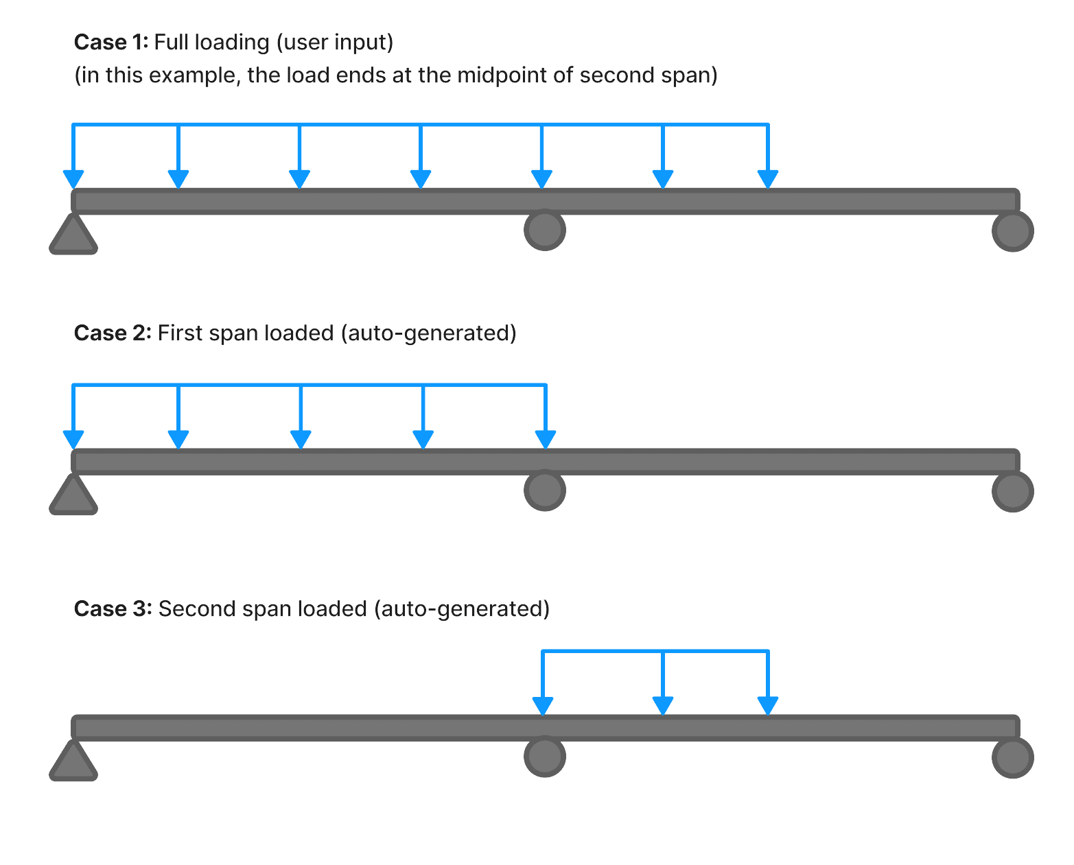
The image below illustrates an example of a two-span continuous beam where the full load is applied regularly in the loads table, and ClearCalcs automatically generates the other cases. As depicted in the image, for loads that end partway through a span, only that portion will be considered in the auto-generated patterns.
Worked Example: Using ClearCalcs Software
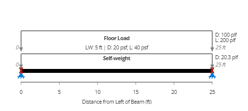
Let's consider a simple example of a 25-foot cantilever beam. By default, when you create a beam design using the Wood Beam Calculator, the beam has supports at both ends.
By moving one support to the 18th foot line, a cantilever span is created that significantly modifies the load dynamics.
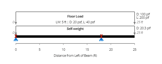
Here, we see a unique load state: load applied to the overhang and the back span at the same time. Most importantly, we need to think about how live loads affect both sections. If the live load is just applied to the overhang, it will deflect and elevate the object significantly; if it is only applied to the back span, it will produce the maximum positive moment.
To tackle these challenges, ClearCalcs has launched a beta version of the live load patterning tool.

Impact Analysis
When we toggle the live load patterning function, we observe tangible changes in our calculations.
There is very little change in the maximum moment, but the deflection is significantly lessened. This emphasizes how important it is to take live load arrangements into account while analyzing structural behavior, especially when it comes to reducing deflection.
For example, when live load patterning is activated, the moment diagram modifies, highlighting the moments' envelope.
The deflection dramatically drops to L/483 from L/2410 without live load patterns, despite the maximum moment staying constant at -7850 lb ft. This highlights the significance of taking live load arrangements into account for correct conclusions, especially in deflection analysis.
| Maximum Moment and Deflection with Live Load Pattern Enabled | Maximum Moment and Deflection with Live Load Pattern Disabled | ||
|---|---|---|---|
 |
 |
||
Navigating Continuous Beam Complexities
Let's analyze a continuous beam configuration with a 40-foot span and an end support.
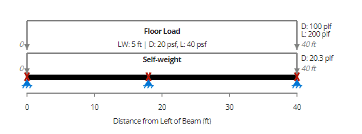
In this case, the load applied to each span individually and to the beam as a whole must be taken into account. Different elements, such the negative moment at the support and the positive moment and shear in other spans, are controlled by the load distribution across the beam.
When live load patterning is enabled, the visualization presents a broader moment envelope, illustrating both positive and negative moments. Conversely, disabling live load patterning results in a narrower envelope, indicating that the entire beam is taken into consideration rather than individual load distributions.
| Moment Diagram with Live Load Pattern Enabled | Moment Diagram with Live Load Pattern Disabled | ||
|---|---|---|---|
 |
 |
||
Navigating Concrete Beam Complexities
When we move on to concrete beams, we get into another level of complexity.
Consider a 60-foot concrete beam with a support placed every 30 feet.
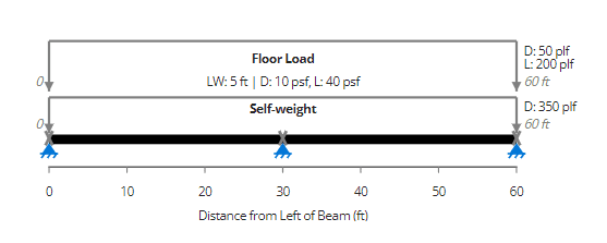
In this scenario, reinforcement is tailored to both positive and negative moments, with wider bars at the bottom for positive reinforcement.
When assessing load distribution, the total floor load is applied throughout the span of the concrete beam.
The important consideration here is the negative moment, which remains constant at 90,000 lb*ft since it is regulated by the load delivered across the entire length of the beam. However, the positive moment varies, with a value of 50,600 pounds increasing to 57, 600 pounds when the live load patterning is enabled.
| Positive and Negative Moment Demand with Live Load Pattern Enabled | Positive and Negative Moment Demand with Live Load Pattern Disabled | ||
|---|---|---|---|
 |
 |
||
Upon turning on live load patterning and analyzing its effect on utilization, a small shift is noticed. When live load patterning is turned off, the utilization is 23%. On the other hand, the utilization goes up to 26% when live load patterning is enabled.
| Moment Capacity with Live Load Pattern Enabled | Moment Capacity with Live Load Pattern Disabled | ||
|---|---|---|---|
 |
 |
||
Despite its seeming slightness, this difference becomes increasingly important in close design scenarios, especially when it comes to long term deflection considerations, notably on cantilevers or overhangs.
Conclusion
In conclusion, mastering live load patterning is essential for structural engineers to ensure the safe and efficient design of structures. By accurately distributing dynamic loads based on real-world usage, engineers can meet code requirements, prevent localized overloading, and optimize material usage. The integration of automated tools, like ClearCalcs, streamlines this process, offering time-saving benefits and reducing the risk of manual errors.
Whether applying live load patterns manually or leveraging software solutions, a thorough understanding of occupancy types, code specifications, and iterative design adjustments remains pivotal for successful structural engineering projects.
Seismic Retrofit Series: URM Insights for US and Canada Engineers
August 5th at 1 pm Eastern Time (ET)
Save your spot →Written by:

.svg)
Reviewed by:


.png)
