In today’s structural engineering practices, software tools have become indispensable for analysing and designing buildings and structures.
However, the effectiveness of these software programs heavily depends on the operator’s ability to input accurate information to ensure that appropriate and correct designs are generated.
In this guide, we’ll delve into the significance of design load combinations in structural engineering, specifically focusing on the standards used in Australia and New Zealand. We’ll explain the different types of loads, discuss critical design states, and provide practical examples for clarity. Additionally, we’ll introduce ClearCalcs, a user-friendly software solution that simplifies the design process for engineers.
Types of loads
So, what specific information is needed to accurately describe the loads and combinations involved in designing buildings?
First let us look at the types of loads which we need to consider:
Dead Loads
These are permanent actions that are supported by the structure throughout its life. They include the self-weight of the structure, all attached materials, permanent equipment, and fittings. These loads are calculated in accordance with the requirements of AS/NZS 1170.1
Live Loads
These are temporary actions that will arise during the life of the structure. They include people, furniture, cars, and any other variable action resulting from the intended use or occupancy of the structure.
Live loads are divided into two types: Distributed loads and concentrated loads. Both loads must be considered and will act independently over the structure. This means these two types of loads will generate two separate load cases when analyzing the structure.
These loads are calculated in accordance with the requirements of AS/NZS1170.1
- Wind Loads: Loads imposed by action of wind and can be in any direction on the structure. These loads are calculated in accordance with the requirements of AS/NZS 1170.2 or AS 4055 for housing.
- Snow Loads: Loads resulting from the weight of snow on a structure, particularly relevant in Alpine regions. These loads are calculated in accordance with the requirements of AS/NZS 1170.3
- Earthquake Loads: Loads induced by seismic activity, crucial for ensuring structural integrity in earthquake-prone areas. These loads are calculated in accordance with the requirements of AS 1170.4 & NZS 1170.5.
- Earth pressure and liquid pressure actions: Loads exerted by soil and liquid pressures, particularly relevant for below-ground structures or those in contact with water bodies. These loads are calculated in accordance with the requirements of AS/NZS 1170.1 (Section 4) and AS 4678.
The importance of design load combinations
The importance of these factors varies depending on the type of structure and its location.
For instance, when designing buildings, governing load cases typically include gravity, snow, wind, and sometimes earthquake loads.
Underground structures like basements and tunnels prioritize earth and hydrostatic pressures, as well as potential earthquake forces.
Gravity loads play a major role in the design of bridges, while structures in cyclonic regions need to withstand significant wind loads.
Understanding load combinations in structural design
All the loads mentioned above are calculated or entered into a design software as basic unfactored loads. Subsequently, these loads must be combined in various combinations and adjusted with varying factors according to the requirements of AS/NZS 1170.
The Australian & New Zealand standard specifies general procedures and criteria for designing a building or structure in limit states format. During this process, two critical limit states are considered:
Ultimate Limit State Design System (ULS)
Ultimate Limit State (ULS) is the design process for a structure to manage the probability of collapse.
ULS deals with strength, fire, overturning, sliding, buckling, fatigue fracture, etc.
Serviceability Limit State Design System (SLS)
Serviceability Limit State (SLS) is the design process to manage the probability of a structure remaining fit for use without requiring repairs. SLS deals with discomfort to occupancy and/or malfunction caused by excessive deflection, crack width, vibration, leakage, loss of durability, etc.
Load combinations
Load combinations are essential to determine the most critical conditions for which a structure must be designed. AS/NZS 1170.0 Section 4 outlines the factored load combinations that must be considered in structural design. These combinations account for various actions such as dead loads, live loads, wind loads, earthquake loads, snow loads, and others.
Stability
For stability considerations, the design action effect Ed,stb is calculated using the following combinations:
- Net Stabilizing Effects: Ed,stb=0.9G
- Dead Load Only: Ed,stb=1.35G
- Dead and Live Loads: Ed,stb=1.2G+1.5Q
- Dead, Live, and Wind Loads: Ed,stb=1.2G+Wu+ψcQ
- Dead, Live, and Earthquake Loads: Ed,stb=G+Eu+ψeQ
- Dead, Live, and Snow or Earth Pressure Loads: Ed,stb=1.2G+Su+ψcQ
Strength
For strength design, the design action effect Ed is determined using the following combinations:
- Dead Load Only: Ed=1.35G
- Dead and Live Loads: Ed=1.2G+1.5Q
- Dead and Reduced Live Loads: Ed=1.2G+1.5ψlQ
- Dead, Live, and Wind Loads: Ed=1.2G+Wu+ψcQ
- Dead Load with Wind Uplift: Ed=0.9G+Wu
- Dead, Live, and Earthquake Loads: Ed=G+Eu+ψeQ
- Dead, Live, and Snow or Earth Pressure Loads: Ed=1.2G+Su+ψcQ
Serviceability
For serviceability limit state design, the action effects Ed are calculated using:
- Dead Load Only: Ed=G
- Dead and Short-Term Live Loads: Ed=G+ψsQ
- Dead and Long-Term Live Loads: Ed=G+ψlQ
- Dead and Serviceability Wind Loads: Ed=G+Ws
- Dead and Serviceability Earthquake Loads: Ed=G+Es
- Other Serviceability Actions: Include serviceability values of other relevant actions as appropriate.
Where:
- G = Dead Load (Permanent Action)
- Q = Live Load (Imposed Action)
- Wu = Ultimate Wind Load
- Ws = Serviceability Wind Load
- Eu = Ultimate Earthquake Load
- Es = Serviceability Earthquake Load
- Su = Snow Load, Liquid Pressure, or Earth Pressure
- ψc, ψe, ψs, ψl = Combination factors (refer to Table 4.1 of AS/NZS 1170.0)
Notes:
Combination Factors (ψ) account for the reduced probability of certain actions occurring simultaneously. They modify the live load Q in the combinations.
Load combinations worked example
The cantilevered reinforced concrete beam shown in the figure below supports a uniformly distributed dead load G= 30kN/m, including the self-weight of the beam and a uniformly distributed Live Load Q=20kN/m.

Determine the worst-case scenario design loads for:
a) Strength conditions
b) Short-term and Long-Term Serviceability conditions
a) The distributed design loads for strength conditions will be given by:
1.35G
w* = 1.35 x 30 = 40.5kN/m
1.2G+1.5Q
w*= 1.2 x 30 + 1.5 x 20 = 36 + 30 = 66kN/m
Let’s use 1.2G+1.5Q as the governing load combination.
The dead load remains constant across the AB span and BC cantilever, constituting a permanent load.
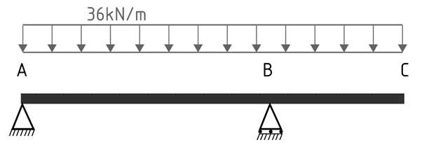
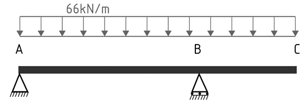
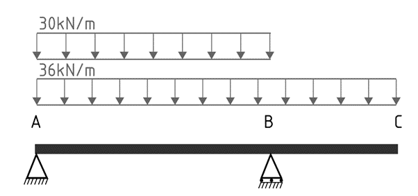
On the other hand, the live load may act over either or both spans. Consequently, there are four potential loading scenarios:
Scenario 1
In the first case, we assume that the live load is not present anywhere along the beam, leaving us only with the factored dead load.
1.2G+1.5Q
w*= 1.2 x 30 + 1.5 x 0 = 36 = 36kN/m
Scenario 2
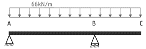
In the second case, we assume the factored dead and live load remains constant across the AB span and BC cantilever.
1.2G+1.5Q
w*= 1.2 x 30 + 1.5 x 20 = 36 + 30 = 66kN/m
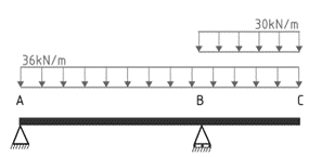
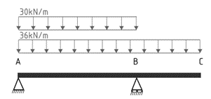
Scenario 3
In the third scenario, we assume the factored dead load is constant across the entire beam while the factored live load acts only along the AB span.
1.2G+1.5Q
w*= 1.2 x 30 + 1.5 x 20 = 36kN/m + 30kN/m
Scenario 4
In the fourth condition, we assume the factored dead load is constant across the entire beam while the factored live load acts only along the BC cantilever.
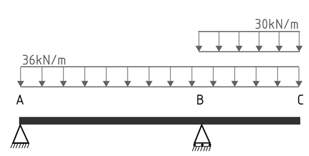
The maximum hogging bending moment at support B will occur when the cantilever carries the maximum load, ie conditions 2 and 4.
The maximum sagging bending moment in span AB will occur when the load over AB is a maximum while the load over the cantilever BC is a minimum, corresponding to condition 3.
b) The short-term and long-term values are given in Table 4.1 of AS1170.0. Let’s assume the beam is in an office building.
Short-term Serviceability conditions: Ψs = 0.7
G+ ΨsQ
ws*= 30 + 0.7 x 20 = 30 + 14 = 44kN/m
Long-term Serviceability conditions: ΨL = 0.4
G+ΨLQ
wL*= 30 + 0.4 x 20 = 30 + 8 = 38kN/m
For this simple case we’ve already encountered a couple of conditions and load cases. Now, imagine a more complex situation involving numerous combinations of dead, live, wind, and earthquake loads applied to various spans. This is where ClearCalcs shines.
Load combinations in ClearCalcs
In every ClearCalcs project, you’ll find a button in the sidebar labeled “Project Defaults”. These defaults consist of preset values utilized by various calculators within the software. They remain consistent across all new calculations created within the project.
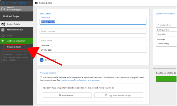
The main sections in Project Defaults are:
Building Site
The wind class obtains the relevant gust pressures from AS 4055:2012 Cl 3.3 and gust wind speeds from Table 2.1(A-B). These values are then used in the Wind Load section of various calculators.
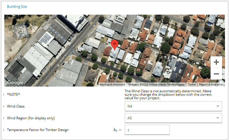
In the design of timber structures, k6 is used as a default temperature factor.
Building geometry (e.g., beam spacings, storey heights, roof slope)
The slope of the roof is set on all calculators for the design of roof beams and the beam and wind analysis calculators. This angle CAN be changed in individual rafter calculators if roof slopes differ throughout the project.

Design criteria / Load Combinations (e.g., default deflection limits, design code)
Deflection limits may be set, which will be defaulted on all calculators where applicable.

Deflection limits must be changed within the individual templates. A hard limit is provided in the Project Defaults, which overrides any span limits that may also be set.
A bearing check is completed for beams. This length is along the length of the beam (i.e., the length of the supporting member/column).
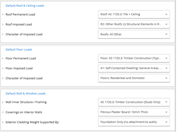
Default Loads (e.g., default roof, floor, wall & window loads)
Default criteria and loading apply to all roof beams, ceilings, floors, and walls. The “Default Loads” table is then used as the default values in several calculators.
Load Cases (e.g., standards-based, custom)
This dropdown menu offers a selection of standards and clauses to determine load combinations. Additionally, you have the option to choose “Custom load combinations” from the bottom of the dropdown list and input your own custom combinations.

You can still override any of these defaults in a specific calculator by selecting the field in question and manually typing over it. These defaults are purely to save you time, and you don’t need to use them if you don’t want to. Any project defaults will be copied along with the calculations if you copy a project.
Conclusion
In summary, load combination in Australia and New Zealand is a fundamental aspect of structural engineering, ensuring buildings and structures are designed to withstand a range of potential loads and environmental conditions.
By adhering to standards like AS/NZS 1170.0, engineers consider various factors such as dead loads, live loads, wind loads, and earthquake loads to determine critical design conditions.
ClearCalcs provides invaluable support throughout this process, offering access to default values, customizable load combinations, and automated calculations. With ClearCalcs, engineers can streamline their workflow, ensure compliance with regulations, and confidently deliver safe and reliable structural designs.
Ready to start calculating in ClearCalcs?
You can use the account for 14 days for free, with no commitment required. Need ClearCalcs for a one-off project? Subscribe to our month-to-month plan and cancel anytime, no questions asked.
Seismic Retrofit Series: URM Insights for US and Canada Engineers
August 5th at 1 pm Eastern Time (ET)
Save your spot →Reviewed by:


.svg)


.png)
