Footings Under Biaxial Bending
Footings Under Biaxial Bending
When designing concrete spread footings, finding its strength part is rather simple, using basic principles of concrete design. Finding the loads to design the footing however can be much trickier, particularly in the case where there is bending in both the X and Y direction simultaneously. This article will go into detail about how ClearCalcs performs these calculations - and how you can do the same by hand if you’re feeling adventurous.
First, let us establish the four main dimensions which the rest of our calculations will depend on. Our footing plan dimensions are defined by the width , parallel to the X axis and the length , parallel to the Y axis.
 The relationships between moment and axial load is best defined by the eccentricities of the load, defined as such:
Note that for ease of calculation, we take the absolute values of moments, which means that the resultant force will always be in the first quadrant. Because of symmetry, the values we get below will all be the same regardless of which quadrant this occurs in.
The relationships between moment and axial load is best defined by the eccentricities of the load, defined as such:
Note that for ease of calculation, we take the absolute values of moments, which means that the resultant force will always be in the first quadrant. Because of symmetry, the values we get below will all be the same regardless of which quadrant this occurs in.
These equations may be easy for a computer to digest, but they are a handful to look at, particularly for zones 2 to 4. Based on the eccentricity limits shown above, we can map five different zones on the footing where, if the eccentricity of the load falls within this area, the shape of the loaded area will correspond to the shapes shown above. This map of the eccentricity zones makes it much easier to see where the eccentricity falls. We generated this map using the Desmos online graphical calculator - see it here!
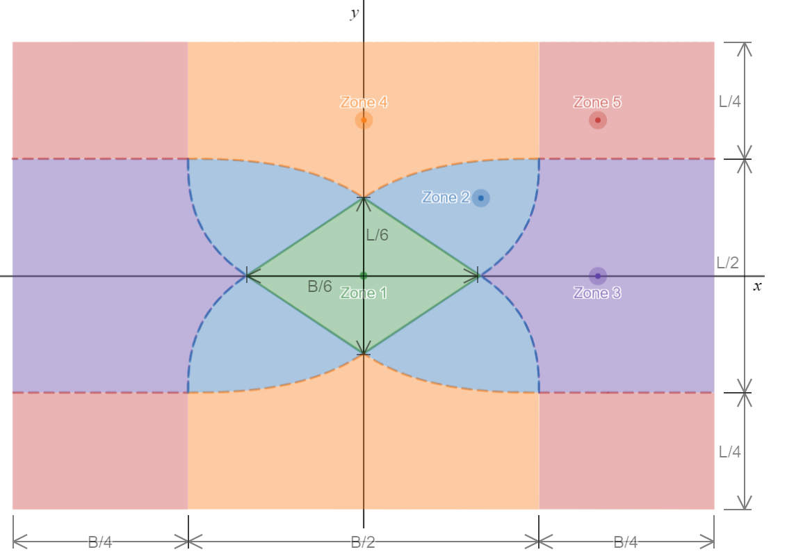 Zones 3, 4 and 5 extend quite far from the center of the footing - in particular, the overturning factor of safety will always be very low if the eccentricity is in zone 5, and the design will be far from efficient.
 This method proves quite convenient later when it comes time to find the footing loads from the bearing pressure, as will be shown later. The three parameters, , and are defined in the sections below. These were derived by Bellos & Bakas using principles of equilibrium and statics.
Once we’ve got our bearing profile properties, we can compare the maximum bearing pressure with our allowable bearing pressure. This is what will govern the plan dimensions of the footing. Once these dimensions are determined, we move on to determine the shear and moment loads on the critical footing section, which we will go over in the next section.
This method proves quite convenient later when it comes time to find the footing loads from the bearing pressure, as will be shown later. The three parameters, , and are defined in the sections below. These were derived by Bellos & Bakas using principles of equilibrium and statics.
Once we’ve got our bearing profile properties, we can compare the maximum bearing pressure with our allowable bearing pressure. This is what will govern the plan dimensions of the footing. Once these dimensions are determined, we move on to determine the shear and moment loads on the critical footing section, which we will go over in the next section.
 This is a special case of a tet with three right angles at the same vertex - this is called a trirectangular tetrahedron. Its volume and centroid are both easy to find:
The problem arises when our tetrahedron extends past the width of the footing or past the critical section, which we define as a distance from the edge of the footing. All of a sudden, our nicely defined tet gets chopped up and these easy properties don’t apply so well. In this case, we need to split our tet into different components, as shown below:
This is a special case of a tet with three right angles at the same vertex - this is called a trirectangular tetrahedron. Its volume and centroid are both easy to find:
The problem arises when our tetrahedron extends past the width of the footing or past the critical section, which we define as a distance from the edge of the footing. All of a sudden, our nicely defined tet gets chopped up and these easy properties don’t apply so well. In this case, we need to split our tet into different components, as shown below:
 We can now see that we have up to four different individual tets which are also trirectangular, labelled from A to D. Tet A contains both B, C and D, while Tet B and Tet C both contain Tet D. This becomes important when we find our footing loads later. Their properties depend on the soil bearing pressure profile, the footing dimensions, and the critical section location, which is normally different for shear and moment.
For shear:
And for moment:
Where is the column length.
We can now see that we have up to four different individual tets which are also trirectangular, labelled from A to D. Tet A contains both B, C and D, while Tet B and Tet C both contain Tet D. This becomes important when we find our footing loads later. Their properties depend on the soil bearing pressure profile, the footing dimensions, and the critical section location, which is normally different for shear and moment.
For shear:
And for moment:
Where is the column length.
And with this, we’ve successfully managed to determine both our bearing pressures and the loads on our footing.
The relationships between moment and axial load is best defined by the eccentricities of the load, defined as such:
Note that for ease of calculation, we take the absolute values of moments, which means that the resultant force will always be in the first quadrant. Because of symmetry, the values we get below will all be the same regardless of which quadrant this occurs in.
Soil Bearing Calculations
These equations are all provided by John Bellos and Nikolaos Bakas in their paper available here, and were independently verified by our team. They are based on first principles of statics and satisfy equilibrium of forces and moments for all cases. The symbol convention we use differs slightly from the paper, but the equations remain the same.Eccentricity Zones
The most difficult part of finding the stress distribution is that since soil cannot resist uplift by tension, at high eccentricities some parts of the footing may lift off the ground and not carry any load. The shape of the area still carrying load will vary based on the eccentricity of the loads, and will correspond to one of the five shapes shown below.| Zone | Shape of Loaded Area | Eccentricity Limits |
|---|---|---|
| 1 |  | |
| 2 |  | and and |
| 3 |  | and |
| 4 |  | and |
| 5 |  | and |
Zones 3, 4 and 5 extend quite far from the center of the footing - in particular, the overturning factor of safety will always be very low if the eccentricity is in zone 5, and the design will be far from efficient.
Bearing Pressure Profile
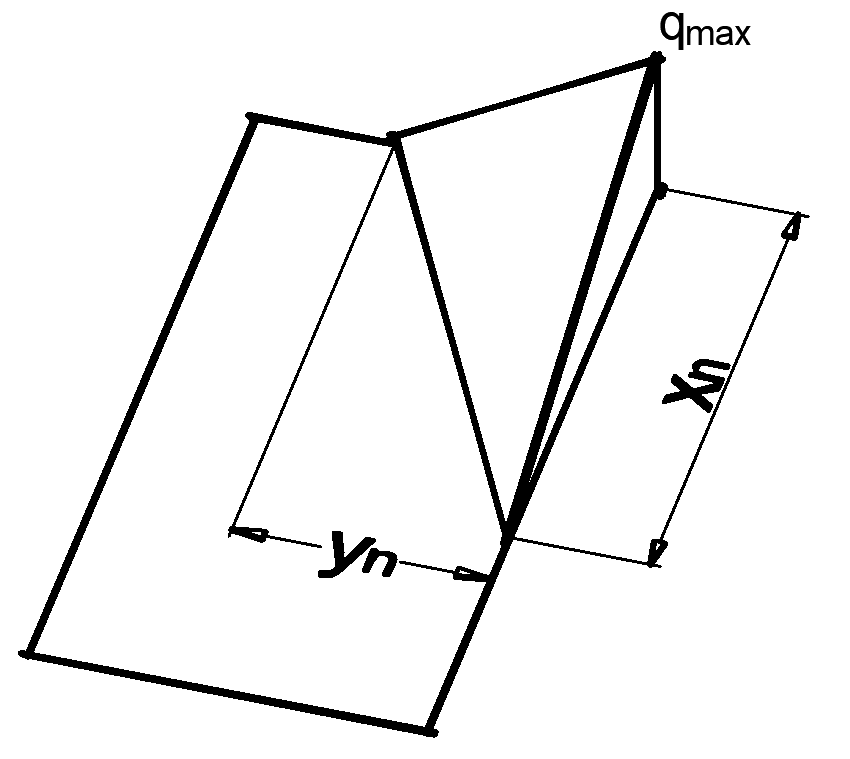
Once we’ve identified the eccentricity zone, we know the shape that our bearing area will take. At this point, we now need to define it. In their paper, Bellos & Bakas define the bearing area with 3 points - the maximum bearing pressure (), and the two intercepts of the zero pressure line (the neutral axis of the footing) with the axes formed by the two upper-right edges of the footing ( and ). The intercepts can be outside the footing (low eccentricity) or inside (high eccentricity).
This method proves quite convenient later when it comes time to find the footing loads from the bearing pressure, as will be shown later. The three parameters, , and are defined in the sections below. These were derived by Bellos & Bakas using principles of equilibrium and statics.
Once we’ve got our bearing profile properties, we can compare the maximum bearing pressure with our allowable bearing pressure. This is what will govern the plan dimensions of the footing. Once these dimensions are determined, we move on to determine the shear and moment loads on the critical footing section, which we will go over in the next section.
Zone 1
This is the zone with the lowest eccentricity, where the entire footing is under compression. The intercepts are given by: and The maximum bearing pressure:Zone 2
This is the troublesome zone, where there is no closed-form solution - this case requires solving a system of two 6th order polynomials - so we must use a numerical solving method (ClearCalcs makes use of the multivariate Newton’s method). First we solve for the two intercepts using the system of equation below: and Using the Newton method, this converges extremely quickly - 3 iterations is almost always enough to get less than 1% error. Once this is solved, we can find :Zone 3
This is the case where eccentricity in the direction is much larger than in the direction. Finding the intercepts: and We can then find the maximum bearing pressure:Zone 4
This is the same as Zone 3, except that the and eccentricities are reversed. Finding the intercepts: and We can find the maximum bearing pressure:Zone 5
This is perhaps the easiest zone to calculate, and these equations can easily be derived graphically by using properties of tetrahedrons. Finding the intercepts: and The maximum bearing pressure is also found:Footing Loads
Finding the loads acting on the concrete footing is the next step in our design - this is used to determine the thickness of the footing and the reinforcement required. The general basis of the procedure is that we must find the volume under the bearing pressure profile to find the total shear load, and its centroid to find the bending moment. In general, most software packages make use of double or triple integration which is performed numerically. This however is relatively slow and more importantly, is very “black-boxy”, which we try to avoid as much as we can. Thus, we derived our own method of finding shear and moment loads on the footing, which we will explain below.Using Tetrahedrons to Represent the Bearing Pressure Profile
If we look at the bearing profile below, we can clearly see that what we have is a tetrahedron (tet), of height and a base of dimensions .
This is a special case of a tet with three right angles at the same vertex - this is called a trirectangular tetrahedron. Its volume and centroid are both easy to find:
The problem arises when our tetrahedron extends past the width of the footing or past the critical section, which we define as a distance from the edge of the footing. All of a sudden, our nicely defined tet gets chopped up and these easy properties don’t apply so well. In this case, we need to split our tet into different components, as shown below:
We can now see that we have up to four different individual tets which are also trirectangular, labelled from A to D. Tet A contains both B, C and D, while Tet B and Tet C both contain Tet D. This becomes important when we find our footing loads later. Their properties depend on the soil bearing pressure profile, the footing dimensions, and the critical section location, which is normally different for shear and moment.
For shear:
And for moment:
Where is the column length.
Tet A
This is the simplest one to find - it is the ideal tet we defined above. The only difference is that we now define our centroid by its distance from the critical section, whereas it was previously defined by its distance from the footing edge.Tet B
This tet is associated with a lower value of . It shows up when: The width is easy to find, but to find the length and height, we use similar triangles. We obtain our volume: To find our centroid, we know that it is at one quarter of the length of the tet away from the footing edge. Thus the centroid about the critical section:Tet C
This tet is associated with a lower value of . It shows up when: In this case, the length is easy to find, but to find the width and height, we use similar triangles. We obtain our volume: We find the centroid about the critical section, but in this case, it is below the critical section so we add a negative sign:Tet D
This tet only shows up in cases of low eccentricities, when the length of Tet B is greater than the distance to the critical section: This is by far the trickiest one to find, stuck inside both Tet B and Tet C. But this also means we can use some of their properties to make our life easier. For the volume: Finding the centroid, which is also below the critical section:Finding the actual footing loads
With our four tets defined, our goal is to find the total shear load at the critical section, and the moment about the critical section. For both parameters, we need to integrate the bearing pressure distribution to find the total force (for shear) and take the moment of the pressure distribution about the critical axis for the bending moment. In practice we do the latter by multiplying the volume of each tet by the distance from its centroid to the critical point. For each tet, we need to be aware of the sign of the distance from the centroid to the critical section:- Tet A extends past the critical section, past the centroid - its volume contributes negatively to the moment about the critical section
- Tet B extends past the critical section, past the centroid - it contributes negatively to the moment
- Tet C is contained within the critical section - it contributes positively to the moment about the critical section
- Tet D is contained within the critical section - it contributes positively to the moment
 | and |
 | and |
 | and |
 | and |
 | and |