Free Diaphragm Analysis Calculator
The free diaphragm analysis calculator lets users enter wind or seismic lateral loads, and get the max shear in their diaphragm as well as the loads going into braced wall lines (eg shear walls, portal frames, etc)
Start your free ClearCalcs trial to unlock linking to other calculators, saving and export, as well as even more calculators for wood, steel, and concrete beams, columns, and footings.
Get More Functionality with a Free ClearCalcs Trial
Experience the full power of ClearCalcs with a 14 day free trial and start being more productive.
How to Use The Free Diaphragm Analysis Calculator
The ClearCalcs Diaphragm Analysis allows users to quickly analyze diaphgrams in a few simple steps.
Currently, only flexible diaphragms are supported. The forces on the flexible diaphragm are distributed to the vertical resisting elements according to the tributary area and simple beam analysis. This generally applies to wood-sheathed diaphragms.
Signing up for a ClearCalcs account will unlock further advanced features for the design and analysis of diaphragms and a variety of other structural elements. ClearCalcs enables users to analyze diaphragms and link to Wind Load Analysis Seismic Analysis for lateral load linking.
The sheet is divided into three main sections:
- ‘Key Properties’, where the user inputs the geometry of their diaphragm and positions of braced wall lines.
- ‘Loads’, where the user can input lateral loads such as wind and seismic,
- ‘Summary’, which displays the key outputs and diagrams.
A ‘Comments’ section is also included for the user to leave any specific design notes. Clicking on any of the input/property labels gives a descriptive reference explanation.
1. Input Key Properties
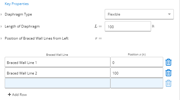
The properties of the diaphragm are specified by typing directly into the input fields.
Length of Diaphragm is the total length of the diaphragm perpendicular to the loading direction that it is being considered.
Position of Braced Wall Lines from Left allow users to enter the braced wall line location. The position (x) is the distance of the centre of wall line from the left of the diaphragm. Any number of additional wall lines may be added.
2. Input Loads
The calculator allows users to input lateral loads like wind loads or seismic loads in pounds per linar foot manually to the diaphragm analysis. Each load can be named by the user.
A line load is a continuous length of the beam which is loaded. This load may start and end at any location. A partially distributed load (PDL), for example, would start and/or end at a location within the beam.
Note also that the start and end magnitudes may differ. A variable distributed load (VDL)is a triangular load, in which the start magnitude does not equal the end magnitude. Note that all distributed loads entered in this table are applied perpendicular to the beam (regardless of its orientation).
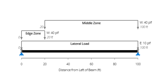
The example diagram below shows a diaphragm with seismic load and wind loads applied to the diaphragm's Edge Zone and Middle Zone.
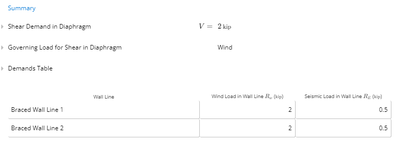
3. Calculation Summary Outputs
Once the loading and geometry have been specified, the calculator automatically uses the ClearCalcs finite element analysis engine to determine the shear demand in diaphragm.
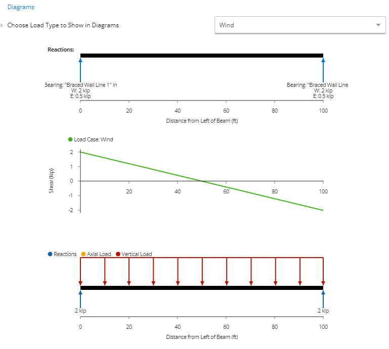
Users can also determine the governing load for shear in the diaphragm as well as view the demands values which demonstrates the total seismic and wind loads being transferred into each braced wall line.
Using the cursor to hover over any point on the shear diagram gives the specific values at that location along the braced wall line.