Kyle Conway
Structural Analysis of Portal Frames: Worked Examples and Case Studies
In this article, we will explore the approach to analyzing portal frames with hand calculations and FEA-based software like ClearCalcs’ Portal Frame Analysis Wizard to showcase how you can accomplish complex analyses in a matter of minutes, saving valuable time and resources.
The complexities of portal frame design can make the structural analysis and design process time-consuming for structural engineers. The “trick” is to leverage the capabilities of advanced Finite Element Analysis (FEA) software to optimize your structural analysis workflow.
In this article, we will explore the approach to analyzing portal frames with hand calculations and FEA-based software like Portal Frame Analysis Wizard to showcase how you can accomplish complex analyses in a matter of minutes, saving valuable time and resources. We will also review a number of innovative portal frame use cases in real-world residential and commercial projects.
For more resources on portal frame design, check out these other guides and resources:
- Mastering Portal Frames: Types and Design Considerations
- How to Analyze a Portal Frame in ClearCalcs
- Worked Example of Portal Frame Analysis in ClearCalcs
Introduction
The analysis of portal frames involves a series of steps to determine the internal forces and verify the structural stability.
The process begins with load determination, where the applied loads are calculated based on the relevant standards and project-specific requirements. These loads are then used to assess the internal forces and bending moments within the frame.
Various methods can be employed for the analysis of portal frames.
- The moment distribution method is a widely used hand calculation technique that allows for the evaluation of member forces and deflections.
- However, with the advancements in technology, computer-aided structural analysis software has become increasingly popular. Finite element method (FEM) software enables more complex analysis, considering nonlinear behavior and precise modeling of materials and connections.
Tools like the Portal Frame Analysis Wizard calculator allow users to swiftly analyze single or multi-bay 2D portal frames in any material, saving significant time and effort. Whether it's a flat, gable, arch, or tied portal frame design, the calculator accommodates a variety of geometries, making it ideal for quick and straightforward designs.
By simply providing the width, leg height, and loads, ClearCalcs automatically determines the necessary nodes and fixities, enabling a comprehensive finite element analysis encompassing moment, shear, axial loads, and displacement.
Design Example: Residential Portal Frame by Hand
Let's perform the actual numerical calculations for the residential portal frame design example, considering a clear span of 30 feet, a frame height of 12 feet, and a roof slope of 6:12.
Step 1: Load Calculation
In this example, we will focus on wind loads which are typically critical in a portal frame design.
Let's assume a wind speed of 120 mph and an exposure category of B.
Using the local building codes (ASCE 7-22: Minimum Design Loads for Buildings and Other Structures), we determine the design wind pressure.
Let's assume it to be 20 psf.
Step 2: Internal Force Calculation
Assuming the wind load acts as a distributed load on the roof, we can calculate the internal forces within the portal frame.
The total wind load on the roof can be calculated as follows:
- Total Wind Load = Wind Pressure x Roof Area
- Total Wind Load = 20 psf x (30 ft x 15 ft) [assuming a triangular roof shape]
- Total Wind Load = 9000 lbs/ft
To calculate the bending moment at the base of the columns, we can assume equal distribution of the total wind load on both sides of the frame (note: a more detailed assessment would use the moment distribution method rather than making this assumption).
Therefore, the bending moment at the base of each column is:
- Bending Moment = (Total Wind Load/2) x (30 ft/2)
- Bending Moment = 9000 lbs/ft x 15 ft
- Bending Moment = 135,000 ft-lbs
Note, external forces also need to be checked and these need to be considered across the tributary width (depth) of each bay.
Step 3: Member Selection and Sizing
Based on the calculated bending moment, we need to select an appropriate steel section for the columns and beam.
Let's assume we select a W10x30 section for the columns. The properties of this section can be obtained from the AISC steel manual.
For the beam, we can select a W12x35 section. Again, the properties of this section can be obtained from the AISC steel manual.
Step 4: Stability Analysis
To ensure stability, we need to check the slenderness ratio of the columns. Let's assume the effective length of the columns is 12 feet (considering fixed supports at the top).
The slenderness ratio can be calculated using the formula:
- Slenderness Ratio = (Effective Length of Column) / (Radius of Gyration)
- Slenderness Ratio = 12 ft / 2.48 in (for W10x30 section) [Radius of Gyration obtained from AISC manual]
The AISC provides limits on the slenderness ratio, and if the calculated value exceeds these limits, additional bracing may be required.
Step 5: Connection Design
For connection design, let's assume we use moment-resisting connections at the base of the columns. These connections provide additional stability and rigidity to the frame.
The design of moment-resisting connections involves checking the required connection capacities, such as shear capacity, moment capacity, and axial capacity, based on the design loads and selected steel sections.
These calculations involve complex analysis and are beyond the scope of this example.
Step 6: Verification and Review
Once the design calculations are completed, it is important to review and verify the design for compliance with US standards. This involves checking the adequacy of the selected sections, stability analysis, and overall structural integrity.
Software tools like ClearCalcs can assist in the verification process by performing automated checks based on the input parameters and design requirements.
Please note that the above calculations are simplified for demonstration purposes, and an actual design would require more comprehensive analysis and consideration of various factors.
Design Example: Residential Portal Frame Using ClearCalcs
For a complete and accurate design it is recommended that engineers use software like the Portal Frame Analysis Wizard calculator.
Let’s work through an example where there is 1 bay that has a width of 30 feet. The leg heights are both 12 feet. The apex is 15 feet from the left leg and is 19.5 feet from the base. The portal frames use W12X35 members.
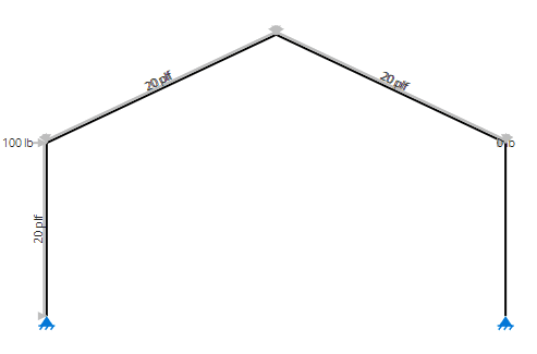
There is 20plf of distributed load on the vertical chords, the chords perpendicular to the member, and also 20plf inward distributed load on the left leg.
Step 1: Input Portal Frame Geometry
All the parameters for the portal frame geometry are input from the sketch above.
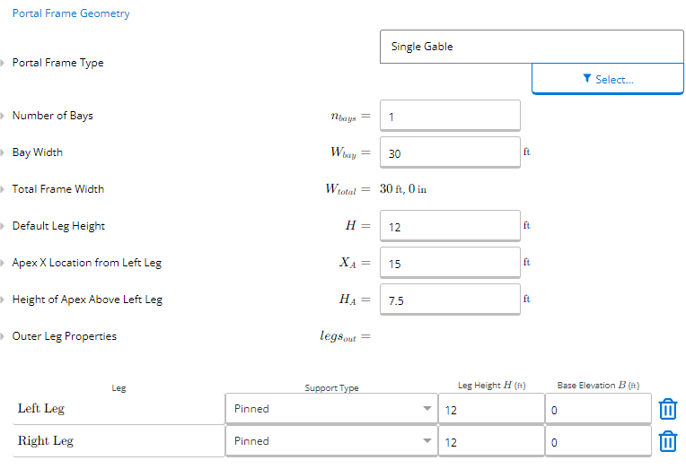
Typically they are specified by the architect and are restricted by land boundaries (bay width) or local building height requirements (leg height, height of apex).
Most portal frames are single gables, but there can be other types as detailed in the article Mastering Portal Frames: Types and Design Considerations.
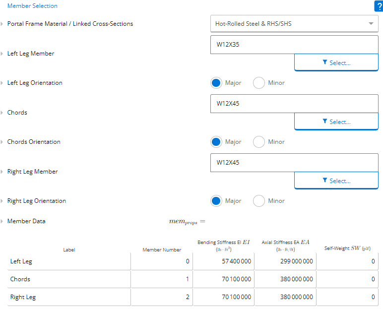
Step 2: Member Selection
ClearCalcs has an in-built member selection tool that has standard hot-rolled steel, cold-formed steel, and timber sections built in to speed up the design process and ensure that the members that are specified in the design can be procured by the builders.
Step 3: Input Loads
Our example calls for 20plf of distributed load on the vertical chords, the chords perpendicular to the member, and also 20plf inward distributed load on the left leg.

Point loads can also be input but are not applicable to our example.
Step 4: Summary Results
ClearCalcs summarises the key actions on the system as per the below tables.
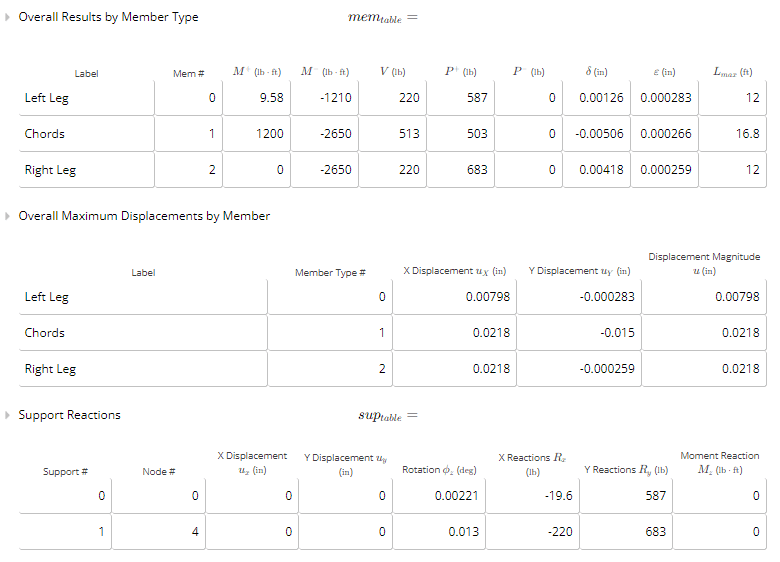
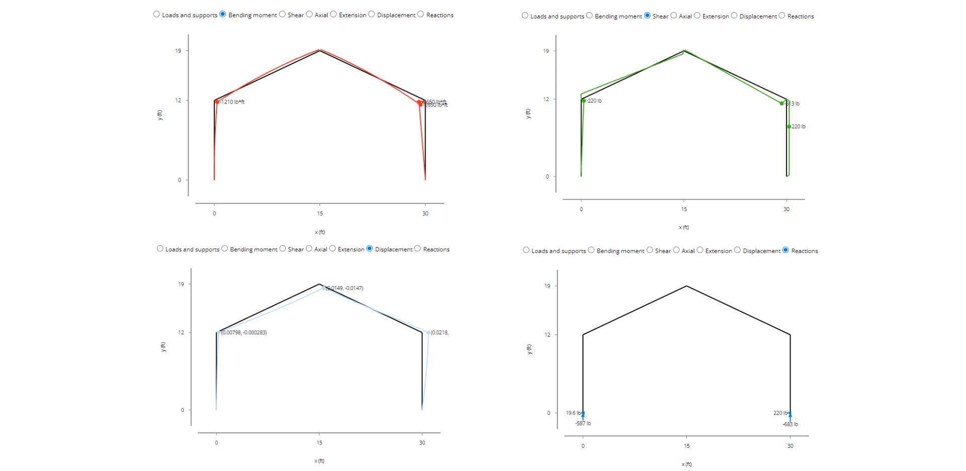
ClearCalcs also provides a graphical representation of the bending moment, shear force, axial load, extension, displacement, and reaction forces at all points along the portal frame, which is incredibly difficult to do by hand and helps to understand the behavior of the structure under the applied loads.
Users can then complete their Portal Frame member design using these outputs and inputting them into the Member (Design Only) calculator such as the wood member design calculator or the steel member design calculator.
Key Challenges in Portal Frame Analysis
Portal frame analysis presents challenges that structural engineers, architects, and building designers must address. Some common challenges specific to portal frame analysis include:
Geometric Nonlinearity
Portal frames often experience large deformations and displacements, especially under lateral loads.
Analyzing and accounting for geometric nonlinearity can be challenging, as it requires considering the changing shape and stiffness of the structure as it deforms. Nonlinear analysis methods, such as the finite element method (FEM), may be necessary to accurately capture the behavior of the frame.
Member Axial-Bending Interaction
Portal frame members, such as columns and beams, often undergo both axial forces (compression or tension) and bending moments simultaneously. The interaction between these axial and bending forces can affect the behavior and capacity of the members.
Accurately capturing and analyzing this interaction is crucial for the overall stability and strength of the portal frame.
Connection Behavior
Connections between portal frame members play a significant role in load transfer and overall frame performance. The behavior of moment-resisting connections, such as bolted or welded connections, can be complex and challenging to model accurately.
It is important to consider connection stiffness, strength, and rotational capacity when analyzing the frame.
Lateral Load Distribution
Portal frames are designed to resist lateral loads, such as wind or seismic forces. However, distributing these lateral loads across the frame can be challenging due to the frame's inherent stiffness and moment-resisting characteristics.
Analyzing and ensuring that the loads are adequately distributed to each member and connection is crucial for a structurally sound design.
Dynamic Effect
In certain cases, portal frames may be subject to dynamic loads, such as vibrations from equipment or machinery within the building. Analyzing the dynamic response of the frame and assessing its impact on the structural performance requires specialized analysis techniques, such as modal analysis or response spectrum analysis.
Second-Order Effects
Portal frames are susceptible to second-order effects, which arise from the interaction between member deformations and structural stiffness. These effects can lead to additional moments and displacements that need to be accounted for in the analysis.
Neglecting second-order effects can result in an inaccurate assessment of the frame's behavior and capacity.
Construction Sequence and Temporary Loads
Portal frames are often erected in a staged construction process, with temporary loads applied during construction. Analyzing the frame's behavior under temporary loads and considering the effects of construction sequence and erection methods are crucial for ensuring stability and safety during the construction phase.
Real-Life Design Examples and Case Studies
Residential Project: Green Hills Residence
The Green Hills Residence is a prime example of innovative portal frame design in a residential project. The design team aimed to create a spacious and visually appealing living space while ensuring structural efficiency.
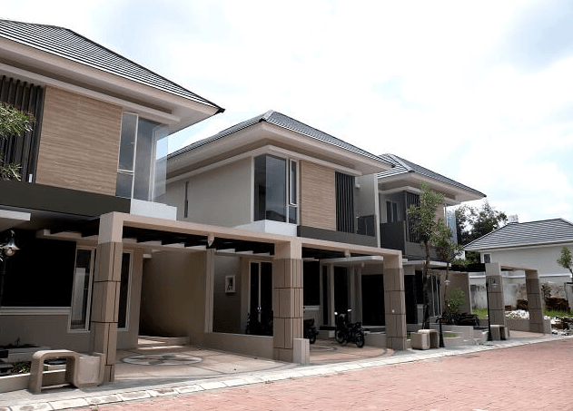 Figure 1: An example of residential projects utilising portal frames (Image Credit)
In this project, the portal frame design allowed for a large open living area with minimal interior columns, providing flexibility for interior layout and aesthetics. The frame was designed to withstand both wind and seismic loads as per the local building codes.
To achieve structural efficiency, the design team opted for a hybrid construction approach using a combination of steel portal frames and lightweight timber infill walls. This combination allowed for optimal utilization of materials, reducing construction costs while maintaining structural integrity.
The portal frames were designed using advanced analysis software, considering load combinations, member sizing, and stability analysis. The result was a durable and efficient structure that met the requirements of the residential project while showcasing innovative design approaches.
Light Commercial Project: Industrial Warehouse
The design of an industrial warehouse often requires large clear spans and high load-carrying capacities. Portal frames offer an ideal solution for such projects, enabling efficient use of space and structural stability.
In a recent industrial warehouse project, a portal frame design was employed to achieve the desired functional requirements while optimizing structural efficiency. The project involved a clear span of 60 feet and a height of 20 feet.
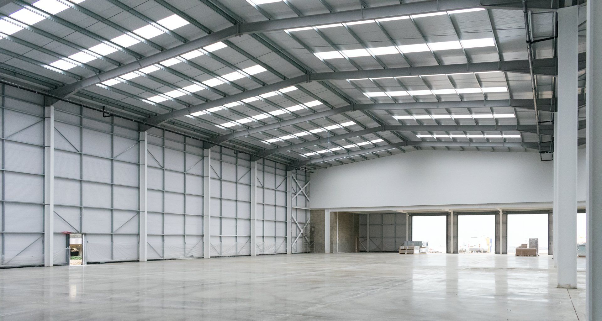 Figure 2: An example of an industrial project using portal frames (Image Credit)
To ensure structural integrity, the portal frames were designed using high-strength steel sections with moment-resisting connections at the base. The frames were subjected to rigorous analysis considering wind loads, seismic loads, and live loads as per the applicable building codes.
To enhance material efficiency, the design team utilized the concept of tapered portal frames. By varying the section sizes along the height of the frame, excess material usage was minimized while maintaining the required strength and stiffness.
The successful completion of this light commercial project demonstrated the application of portal frame design principles in achieving optimal structural efficiency, load-carrying capacity, and cost-effectiveness.
Mixed-Use Project: Harbour Plaza
Harbour Plaza is a mixed-use development that seamlessly integrates residential and light commercial spaces. The design concept called for an open and inviting layout, and portal frames played a significant role in realizing this vision.
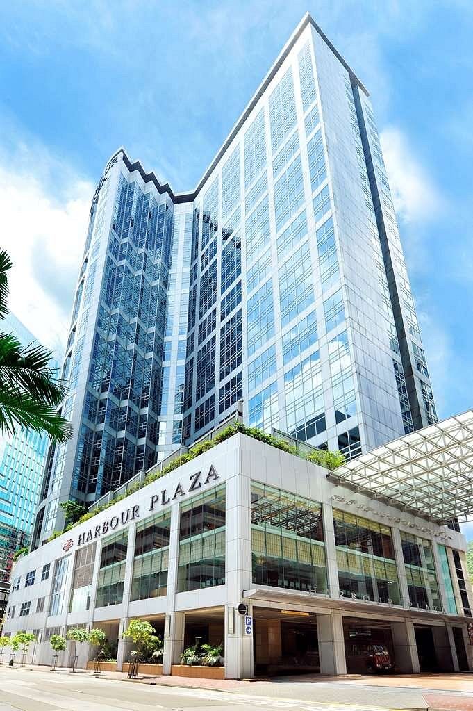
Figure 3: An example of mixed use development project utilizing portal frames (Image Credit)
In this project, portal frames were used to create expansive storefront areas for shops and restaurants on the ground floor. The frames provided ample natural light and unobstructed views, enhancing the overall aesthetics of the building.
To ensure the structural stability and safety of the portal frames, wind loads and seismic loads were carefully considered during the design phase. The frames were designed with moment-resisting connections and suitable steel sections to withstand the applied loads.
In terms of material choices, the design team prioritized sustainability and opted for high-performance steel with recycled content. This allowed for a reduced environmental footprint while maintaining structural integrity and durability.
The successful completion of Harbour Plaza highlighted the versatility of portal frames in mixed-use projects, offering both structural efficiency and architectural appeal.
Conclusion
The complexities of portal frame design have traditionally made the structural analysis and design process time-consuming for engineers. However, with advanced FEA-based software, engineers can optimize their workflow, achieve complex analyses in less time, and save valuable resources to develop more innovative projects.
For more resources on portal frame design, check out these other guides and resources:
- Mastering Portal Frames: Types and Design Considerations
- How to Analyze a Portal Frame in ClearCalcs
- Worked Example of Portal Frame Analysis in ClearCalcs
Disclaimer: The case studies mentioned in the article is solely based on the personal experience of the writer. Due to confidentiality we are unable to provide more specific details or links related to the project.
Sign up today. No credit card required.
Experience the full power of ClearCalcs with a 14 day free trial and start being more productive.